-
LM3477 Buck Controller Evaluation Module User's Guide
LM3477 Buck Controller Evaluation Module User's Guide
Trademarks
All trademarks are the property of their respective owners.
1 Introduction
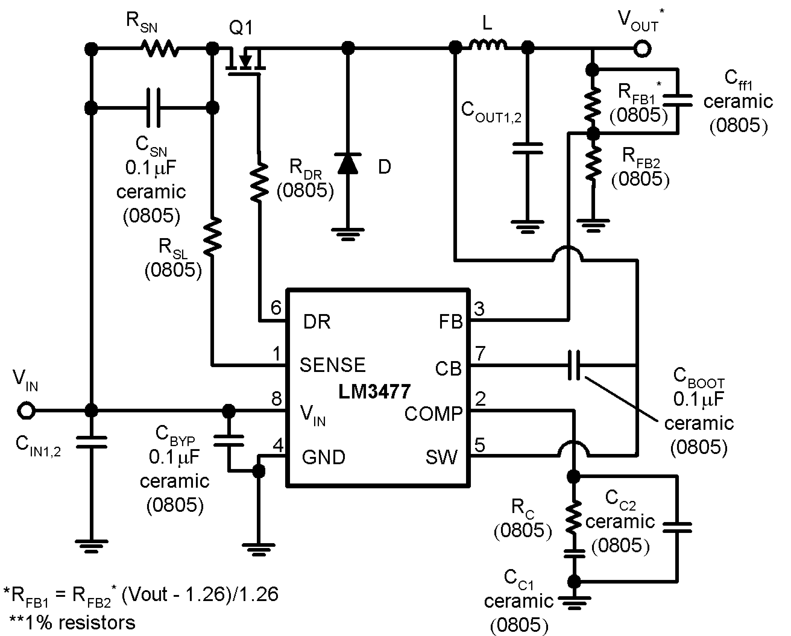
The LM3477 is a current mode, high-side N channel FET controller. It is most commonly used in buck configurations, as shown in Figure 1-1. All the power conducting components of the circuit are external to the LM3477, so a large variety of inputs, outputs, and loads can be accommodated by the LM3477.
The LM3477 evaluation board comes ready to operate at the following conditions:
- 4.5 V ≤ VIN ≤ 15 V
- VOUT = 3.3 V
- 0 A ≤ IOUT ≤ 1.6 A
The circuit and BOM for this application are given in Figure 1-1 and Table 1-1.
 Figure 1-1 LM3477 Buck Converter
| Component | Value | Part Number |
|---|---|---|
| CIN1 | 120 µF/20 V | 594D127X0020R2 |
| CIN2 | No connect | |
| COUT1 | 22 µF/10 V | LMK432BJ226MM (Taiyo Yuden) |
| COUT2 | 22 µF/10 V | LMK432BJ226MM (Taiyo Yuden) |
| L | 10 µH, 3.8 A | DO3316P-103 (Coilcraft) |
| RC | 1.8 kΩ | CRCW08051821FRT1 (Vitramon) |
| CC1 | 12 nF/50 V | VJ0805Y123KXAAT (Vitramon) |
| CC2 | No connect | |
| Q1 | 5 A, 30 V | IRLMS2002 (IRF) |
| D | 100 V, 3 A | MBRS340T3 (Motorola) |
| RDR | 20 Ω | CRCW080520R0FRT1 (Vitramon) |
| RSL | 1 kΩ | CRCW08051001FRT1 (Vitramon) |
| RFB1 | 16.2 kΩ | CRCW08051622FRT1 (Vitramon) |
| RFB2 | 10.0 kΩ | CRCW08051002FRT1 (Vitramon) |
| CFF | 470 pF | VJ0805Y471KXAAT (Vitramony) |
| RSN | 0.03 Ω | WSL 2512 0.03 Ω ±1% (Dale) |
2 Performance
Figure 2-1 to Figure 2-2 show some benchmark data taken from the circuit above on the LM3477 evaluation board. This evaluation board can also be used to evaluate a buck regulator circuit optimized for a different operating point or to evaluate a trade-off between cost and some performance parameter. For example, the conversion efficiency can be increased by using a lower RDS(ON) MOSFET, ripple voltage can be lowered with lower ESR output capacitors, and the hysteretic threshold can be changed as a function of the RSN and RSL resistors.
The conversion efficiency can be increased by using a lower RDS(ON) MOSFET, however, it drops as input voltage increases. The efficiency reduces because of increased diode conduction time and increased switching losses. Switching losses are due to the Vds × Id transition losses and to the gate charge losses, both of which can be lowered by using a FET with low gate capacitance. At low duty cycles, where most of the power loss in the FET is from the switching losses, trading off higher RDS(ON) for lower gate capacitance will increase efficiency.
 Figure 2-1 Efficiency vs Load VOUT =
3.3 V
 Figure 2-2 Efficiency vs VIN
VOUT = 3.3 V, IOUT = 2 A
Figure 2-2 Efficiency vs VIN
VOUT = 3.3 V, IOUT = 2 AFigure 3-1 shows a bode plot of LM3477 open loop frequency response using the external components listed in Table 1-1.

3 Hysteretic Mode
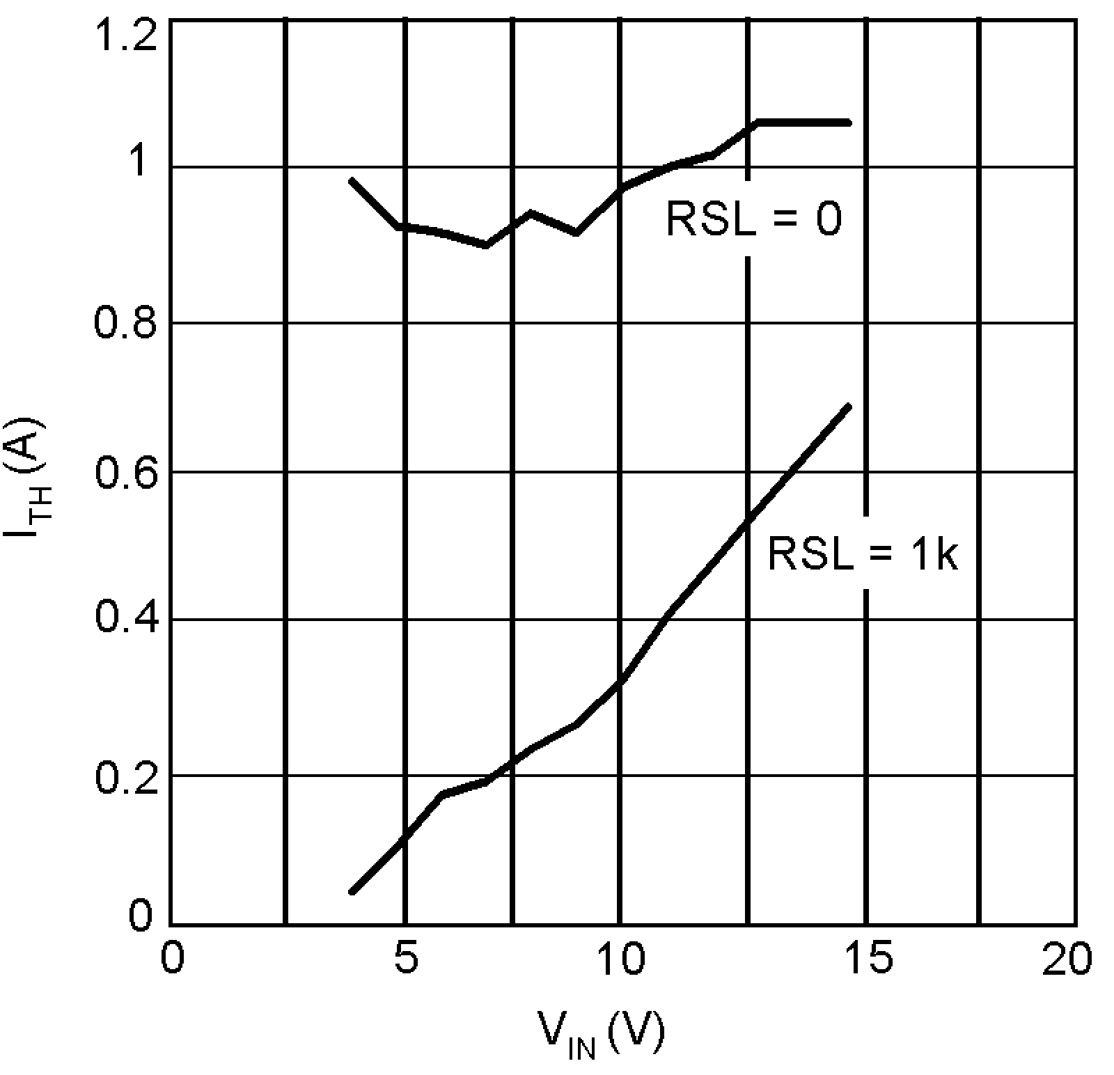
As the load current is decreased, the LM3477 will eventually enter a 'hysteretic' mode of operation. When the load current drops below the hysteretic mode threshold, the output voltage rises slightly. The overvoltage protection (OVP) comparator senses this rise and causes the power MOSFET to shut off. As the load pulls current out of the output capacitor, the output voltage drops until it hits the low threshold of the OVP comparator and the part begins switching again. This behavior results in a lower frequency, higher peak-to-peak output voltage ripple than with the normal pulse width modulation scheme. The magnitude of the output voltage ripple is determined by the OVP threshold levels, which are referred to the feedback voltage and are typically 1.25 V to 1.31 V. For more information, see the Electrical Characteristics table in the LM3477 High Efficiency High-Side N-Channel Controller for Switching Regulator Data Sheet. In the case of a 3.3-V output, this translates to a regulated output voltage between 3.27 V and 3.43 V. The hysteretic mode threshold point is a function of RSN and RSL. Figure 3-1 shows the hysteretic threshold versus VIN for the LM3477 evaluation board with and without RSL.
 Figure 3-1 ITH vs
VIN