-
LM3643 Synchronous Boost Dual LED Flash Driver with 1.5-A High-Side Current Sources
- 1 Features
- 2 Applications
- 3 Description
- 4 Simplified Schematic
- 5 Revision History
- 6 Device Comparison Table
- 7 Pin Configuration and Functions
- 8 Specifications
-
9 Detailed Description
- 9.1 Overview
- 9.2 Functional Block Diagram
- 9.3 Feature Description
- 9.4 Device Functioning Modes
- 9.5 Programming
- 9.6
Register Descriptions
- 9.6.1 Enable Register (0x01)
- 9.6.2 IVFM Register (0x02)
- 9.6.3 LED1 Flash Brightness Register (0x03)
- 9.6.4 LED2 Flash Brightness Register (0x04)
- 9.6.5 LED1 Torch Brightness Register (0x05)
- 9.6.6 LED2 Torch Brightness Register (0x06)
- 9.6.7 Boost Configuration Register (0x07)
- 9.6.8 Timing Configuration Register (0x08)
- 9.6.9 TEMP Register (0x09)
- 9.6.10 Flags1 Register (0x0A)
- 9.6.11 Flags2 Register (0x0B)
- 9.6.12 Device ID Register (0x0C)
- 9.6.13 Last Flash Register (0x0D)
- 10Applications and Implementation
- 11Power Supply Recommendations
- 12Layout
- 13Device and Documentation Support
- 14Mechanical, Packaging, and Orderable Information
- IMPORTANT NOTICE
LM3643 Synchronous Boost Dual LED Flash Driver with 1.5-A High-Side Current Sources
1 Features
- 1.5 A Total Allowed LED Current During Operation
(ILED1 + ILED2 = 1.5 A) - Dual Independent LED Current Source Programmability
- Accurate and Programmable LED Current Range from 1.4 mA to 1.5 A
- Optimized Flash LED Current During Low Battery Conditions (IVFM)
- > 85% Efficiency in Torch Mode (@ 100 mA) and Flash Mode (@1 A to 1.5 A)
- Grounded Cathode LED Operation for Improved Thermal Management
- Small Solution Size: < 16 mm2
- Hardware Strobe Enable (STROBE)
- Synchronization Input for RF Power Amplifier Pulse Events (TX)
- Hardware Torch Enable (TORCH/TEMP)
- Remote NTC Monitoring (TORCH/TEMP)
- 400-kHz I2C-Compatible Interface
- LM3643 (I2C Address = 0x63)
- LM3643A (I2C Address = 0x67)
2 Applications
Camera Phone White LED Flash
3 Description
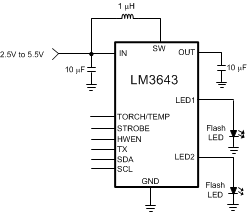
The LM3643 is a dual LED flash driver that provides a high level of adjustability within a small solution size. The LM3643 utilizes a 2-MHz or 4-MHz fixed-frequency synchronous boost converter to provide power to the dual 1.5-A constant current LED sources. The total LED current the LM3643 boost can deliver is 1.5 A (ILED1 + ILED2 ). The dual 128 level current sources provide the flexibility to adjust the current ratios between LED1 and LED2 with each driver capable of delivering a maximum of 1.5 A (ex: ILED1 = 1.5 A and ILED2 = 0FF, ILED1 = 0FF and ILED2 = 1.5 A, or a current configuration with a current less than 1.5 A , ILED1 = 950 mA and ILED2 = 250 mA). An adaptive regulation method ensures the current sources remain in regulation and maximizes efficiency.
Features of the LM3643 are controlled via an I2C-compatible interface. These features include: hardware flash and hardware torch pins (STROBE and TORCH/TEMP), a TX interrupt, and an NTC thermistor monitor. The device offers independently programmable currents in each output leg to drive the LEDs in a Flash or Movie Mode (Torch) condition.
The 2-MHz or 4-MHz switching frequency options, overvoltage protection (OVP), and adjustable current limit allow for the use of tiny, low-profile inductors and (10-µF) ceramic capacitors. The device operates over a –40°C to 85°C ambient temperature range.
Device Information(1)
| PART NUMBER | PACKAGE | BODY SIZE (MAX) |
|---|---|---|
| LM3643 | DSBGA (12) | 1.69 mm x 1.31 mm |
- For all available packages, see the orderable addendum at the end of the datasheet.
4 Simplified Schematic
