Designing with Linear Thermistors
The same hardware and software design methods commonly used with other positive temperature coefficient (PTC) or negative temperature coefficient (NTC) thermistors also apply to silicon-based linear thermistors. In this technical article, I’ll cover some simple hardware and software methods when using silicon-based linear thermistors.
Hardware
One method to generate an output voltage across a silicon-based linear thermistor is to use a voltage divider circuit, as shown in Figure 1. This results in a positive and linear voltage drop (VTemp) response, which is most often routed directly to the analog-to-digital converter (ADC).
 Figure 1 Low-side voltage divider biasing
The bias resistor value should be the resistance at 25°C (R25) of the silicon-based linear thermistor device in use. Table 1 shows the bias resistor values for several TI thermistors.
| Generic part number | Rbias value |
|---|---|
| TMP61 | 10 kΩ |
| TMP63 | 100 kΩ |
| TMP64 | 47 kΩ |
Alternatively, silicon-based linear thermistors can be biased directly using a precision current source, as shown in Figure 2. This method eliminates the need for a bias resistor and provides a greater dynamic voltage drop range.
 Figure 2 Precision current-source biasing
Keep in mind that while voltage and current sources are designed to be constant, they do vary slightly under different operating conditions, which could impact temperature measurement. Luckily, using a ratiometric approach can help negate the effect of power-supply variation because the ADC will read in a value proportional to its own reference voltage. As Figure 3 illustrates, it is possible to tie to the ADC reference voltage when using the voltage divider circuit.
 Figure 3 Ratiometric thermistor circuit
Software
Software for TI’s silicon-based linear thermistors is very simple, and our Thermistor Design Tool makes it even easier by providing resistance vs. temperature (R-T) tables, multiple temperature conversion methods and example code. When using the tool, make sure to select your device and enter your specific circuit parameters.
If you’re using a look-up table (LUT), you’ll find all of the resistance values across temperature under the Device Resistance Tables tab provided both in 1°C and 5°C steps. You can use the Lookup Table or Interpolation From Lookup Table tabs in the tool to get started with TI’s example code. The standard LUT method will round up or down to the nearest value found in the LUT.
The interpolation method in Equation 1 will calculate the temperature in between values found in the LUT for greater precision. Silicon-based linear thermistors can take advantage of interpolation because of their very stable, linear R-T response across temperature.

where X is the measured resistance, Y is the unknown value of temperature, X1 and Y1 are the lower-limit values in the LUT, and X2 and Y2 are the upper-limit values in the LUT.
As an alternative to LUTs, TI recommends using a curve-fit equation known as a fourth-order polynomial regression (Equation 2). Compared to other conversion methods, this equation (shown in Celsius) is very accurate and saves processing time on top of memory.

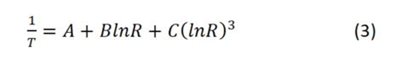
You can find the solved coefficients for your design in the 4th Order Polynomial Regression tab of the Thermistor Design Tool. The tool also provides example code for the Steinhart-Hart equation (Equation 3, shown in Kelvin), a typical method of temperature conversion for thermistors:
The Threshold Detection tab shows you what values you may expect to see from your ADC at specific temperatures for simple threshold monitoring. This method is helpful for applications where continuous temperature collection is unnecessary, but it’s critical for the system to stay above or below a temperature threshold.
Additionally, the Averaging tab explains how averaging your temperature samples can help increase the measurement resolution and signal-to-noise ratio. Using a first-in-first-out sequence, as shown in Figure 4, you can create a running average that calculates the temperature every time a new sample comes into the array.
 Figure 4 FIFO operation
When calculating the average, you would take the sum of all the values in your array and divide by the total number of samples (Equation 4).

Switching to a silicon-based linear thermistor does not require much work, especially if you are already using another type of thermistor. A change required for any type of new thermistor would be in software. Easy to use and very versatile, TI’s linear thermistors come with all of the data and example codes you need, and our team of engineers on the TI E2E™ support forums can help you quickly set up your design. Regardless of your hardware or software preferences, our design tools help you get to market quickly and effectively.
Additional resources
- Look at our thermistor FAQs for frequently asked questions related to industry compliance standards and design specifications.
- Check out TI’s thermistor page to learn more about our silicon-based linear thermistors.
IMPORTANT NOTICE AND DISCLAIMER
TI PROVIDES TECHNICAL AND RELIABILITY DATA (INCLUDING DATASHEETS), DESIGN RESOURCES (INCLUDING REFERENCE DESIGNS), APPLICATION OR OTHER DESIGN ADVICE, WEB TOOLS, SAFETY INFORMATION, AND OTHER RESOURCES “AS IS” AND WITH ALL FAULTS, AND DISCLAIMS ALL WARRANTIES, EXPRESS AND IMPLIED, INCLUDING WITHOUT LIMITATION ANY IMPLIED WARRANTIES OF MERCHANTABILITY, FITNESS FOR A PARTICULAR PURPOSE OR NON-INFRINGEMENT OF THIRD PARTY INTELLECTUAL PROPERTY RIGHTS.
These resources are intended for skilled developers designing with TI products. You are solely responsible for (1) selecting the appropriate TI products for your application, (2) designing, validating and testing your application, and (3) ensuring your application meets applicable standards, and any other safety, security, or other requirements. These resources are subject to change without notice. TI grants you permission to use these resources only for development of an application that uses the TI products described in the resource. Other reproduction and display of these resources is prohibited. No license is granted to any other TI intellectual property right or to any third party intellectual property right. TI disclaims responsibility for, and you will fully indemnify TI and its representatives against, any claims, damages, costs, losses, and liabilities arising out of your use of these resources.
TI’s products are provided subject to TI’s Terms of Sale (www.ti.com/legal/termsofsale.html) or other applicable terms available either on ti.com or provided in conjunction with such TI products. TI’s provision of these resources does not expand or otherwise alter TI’s applicable warranties or warranty disclaimers for TI products.
Mailing Address: Texas Instruments, Post Office Box 655303, Dallas, Texas 75265
Copyright © 2023, Texas Instruments Incorporated