-
Protect Outdoor Cameras from Extreme Weather with a Temperature Switch
Protect Outdoor Cameras from Extreme Weather with a Temperature Switch
Chen Jiao

Because of their role in security applications, it’s important that outdoor cameras do not malfunction or fail, regardless of whether they’re placed in tropical or frigid climates, or climates that experience both extremes in a given day.
Older generations of outdoor cameras can only operate reliably within a specific temperature range. When the temperature is low, a lithium battery’s capacity degenerates rapidly because of its bigger internal resistor and may even fail. When the temperature is high, the camera’s image sensor may produce “hot pixels,” which are bright individual pixels that adversely affect the overall picture quality.
Designing an outdoor camera that can endure environmental temperatures in a wide temperature range – from -30°C to +55°C – comes with two key design challenges, however. The first challenge is the ability to start up when temperatures are extremely low or high. The second challenge is the need to measure temperatures accurately within a wide temperature range, since the operation of a fan or heater installed inside the camera is based on temperature measurements. Accurate temperature results can maximize a camera’s operational temperature range and prevent device failure.
A design with a temperature switch can help resolve both of these challenges.
| Learn more about the TMP390 temperature switch | |

|
Driving industrial innovation with small-size sensors |
How fans and heaters enable efficient operation
Outdoor cameras produce high energy, especially high-definition cameras. When the ambient temperature is high, a fan can decrease the internal temperature to keep the camera operating properly. In extremely cold conditions, although cameras do generate considerable heat, this heat is not enough to keep them working above a minimum operating temperature. Thus, when the temperature is low, a heater can increase the internal temperature.
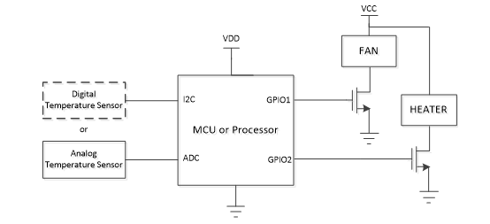
Figure 1 shows a traditional temperature protection design, in which a microcontroller (MCU) or processor starts up first and detects the temperature with the help of sensors. If the temperature is too low or high, however, damage to the MCU or image sensors may result if startup is attempted. To avoid this, an outdoor camera design should restore the camera to its minimum operating temperature before attempting to startup the camera.
 Figure 1 A traditional temperature protection design
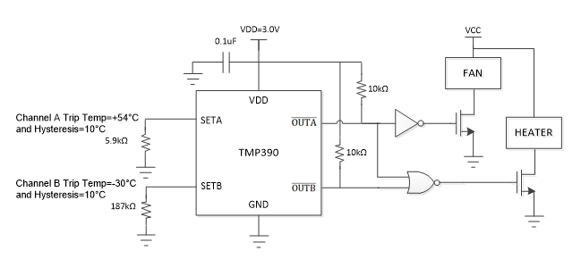
The TMP390 dual-channel temperature switch offers independent over- and under temperature detection without using a MCU. Because the temperature switch controls the fan and heater directly, it can provide proper temperature for the whole system before MCU startup, thus preventing the MCU from operating in extreme high or low temperatures. Resistor-programmable temperature trip points offer flexibility for a variety of applications, while resistor-programmed thermal hysteresis options of 5°C or 10°C prevent undesired digital output switching.
During a startup process (see Figure 2) in extremely low temperatures, after the power turns on, the temperature switch starts up first; the MCU or other components remain off. As the temperature moves out of the safety range, is active low, while the heater and fan start to increase the internal temperature. When the temperature gets to a pre-selected value, the whole system begins the startup process. Compared to the traditional design for temperature protection in Figure 1, the TMP390 temperature switch can regulate the temperature before system startup, thus meeting the challenge to enable startup in extremely low or high temperatures.
 Figure 2 The TMP390 example circuit at +60°C and -40°C thresholds with 10°C hysteresis
The TMP390 temperature switch has 3C accuracy from -55°C to +130°C (±1.5°C from 0°C to +70°C), which provides enough accuracy for a wide temperature range. With accurate temperature measurement, an outdoor camera doesn’t have to leave additional margin for temperature protection, which maximizes the operational temperature range and protects the devices within the system efficiently. Since the TMP390 temperature switch can control the fan or heater accurately, it’s possible to save excessive power in your outdoor camera designs.
IMPORTANT NOTICE AND DISCLAIMER
TI PROVIDES TECHNICAL AND RELIABILITY DATA (INCLUDING DATASHEETS), DESIGN RESOURCES (INCLUDING REFERENCE DESIGNS), APPLICATION OR OTHER DESIGN ADVICE, WEB TOOLS, SAFETY INFORMATION, AND OTHER RESOURCES “AS IS” AND WITH ALL FAULTS, AND DISCLAIMS ALL WARRANTIES, EXPRESS AND IMPLIED, INCLUDING WITHOUT LIMITATION ANY IMPLIED WARRANTIES OF MERCHANTABILITY, FITNESS FOR A PARTICULAR PURPOSE OR NON-INFRINGEMENT OF THIRD PARTY INTELLECTUAL PROPERTY RIGHTS.
These resources are intended for skilled developers designing with TI products. You are solely responsible for (1) selecting the appropriate TI products for your application, (2) designing, validating and testing your application, and (3) ensuring your application meets applicable standards, and any other safety, security, or other requirements. These resources are subject to change without notice. TI grants you permission to use these resources only for development of an application that uses the TI products described in the resource. Other reproduction and display of these resources is prohibited. No license is granted to any other TI intellectual property right or to any third party intellectual property right. TI disclaims responsibility for, and you will fully indemnify TI and its representatives against, any claims, damages, costs, losses, and liabilities arising out of your use of these resources.
TI’s products are provided subject to TI’s Terms of Sale (www.ti.com/legal/termsofsale.html) or other applicable terms available either on ti.com or provided in conjunction with such TI products. TI’s provision of these resources does not expand or otherwise alter TI’s applicable warranties or warranty disclaimers for TI products.
Mailing Address: Texas Instruments, Post Office Box 655303, Dallas, Texas 75265
Copyright © 2023, Texas Instruments Incorporated