An Open-and-shut Case, Part 1: Limitations of Mechanical Case Tamper Detection in Smart Meters
Mekre Mesganaw
To increase system efficiency and reduce revenue loss, utility providers must either prevent or detect when customers are stealing services. A common way to steal service is to tamper with the meters used for billing. Many tamper methods are invasive and require modifications to components inside the meter case, so the first line of defense is the meter case itself. Meter cases should be difficult to open, with an intrusion detection system in place to determine when someone has opened it.
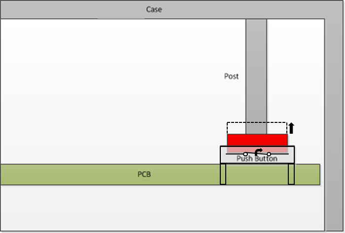
Traditionally, this type of tamper detection functionality was mechanical. As shown in Figure 1, a post on the case physically pushes down on a push-button connected to a general-purpose input/output (GPIO) pin of a microcontroller. When the case is opened, the post releases from the button causing the state of the GPIO pin to change, which would alert the microcontroller that the case was opened.
 Figure 1 Traditional Mechanical Case Tampering Implementation
There are limitations to this mechanical implementation because there are ways to open the case without activating the push-button. There are also durability issues because the push-button can get stuck, thus paralyzing the tamper detection functionality. To mitigate these issues, you could use higher-reliability switches, but that would increase the system cost.
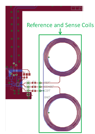
One alternative is to use an implementation with an inductive switch like the LDC0851. The LDC0851 measures the inductance of a sense inductor and a reference inductor and updates the push-pull output depending on which inductance is higher. You can implement the inductors by fabricating coils on the system’s printed circuit board (PCB), as shown in Figure 2.
 Figure 2 Example Reference and Sense Coil PCB Implementation
The switch output of the LDC0851 pulls low when the sense inductance (LSENSE) is sufficiently smaller than the reference inductance (LREF), and similarly pulls high when LSENSE is sufficiently larger than LREF. The LDC0851 also features a threshold adjust mode that modifies the required relationship between LSENSE and LREF for the switching point, which enables fine-tuning of the switching point for a specific distance. Additionally, when a metal approaches the top of one of the coils connected to the LDC0851, the inductance of that coil decreases.
Using this inductance decrease property as well as the operational characteristics of the LDC0851, it’s possible to implement case tamper detection by placing a metal at a fixed distance from the sensors so that the LDC0851 is in a known state. When the meter case is opened, the distance between the coil and the metal changes, causing the output to change states. The microcontroller connected to the LDC0851 would detect and log this change as a case tamper event.
In the next installment of this two-part series, I will discuss the advantages of this new inductive-based method for case tamper detection.
IMPORTANT NOTICE AND DISCLAIMER
TI PROVIDES TECHNICAL AND RELIABILITY DATA (INCLUDING DATASHEETS), DESIGN RESOURCES (INCLUDING REFERENCE DESIGNS), APPLICATION OR OTHER DESIGN ADVICE, WEB TOOLS, SAFETY INFORMATION, AND OTHER RESOURCES “AS IS” AND WITH ALL FAULTS, AND DISCLAIMS ALL WARRANTIES, EXPRESS AND IMPLIED, INCLUDING WITHOUT LIMITATION ANY IMPLIED WARRANTIES OF MERCHANTABILITY, FITNESS FOR A PARTICULAR PURPOSE OR NON-INFRINGEMENT OF THIRD PARTY INTELLECTUAL PROPERTY RIGHTS.
These resources are intended for skilled developers designing with TI products. You are solely responsible for (1) selecting the appropriate TI products for your application, (2) designing, validating and testing your application, and (3) ensuring your application meets applicable standards, and any other safety, security, or other requirements. These resources are subject to change without notice. TI grants you permission to use these resources only for development of an application that uses the TI products described in the resource. Other reproduction and display of these resources is prohibited. No license is granted to any other TI intellectual property right or to any third party intellectual property right. TI disclaims responsibility for, and you will fully indemnify TI and its representatives against, any claims, damages, costs, losses, and liabilities arising out of your use of these resources.
TI’s products are provided subject to TI’s Terms of Sale (www.ti.com/legal/termsofsale.html) or other applicable terms available either on ti.com or provided in conjunction with such TI products. TI’s provision of these resources does not expand or otherwise alter TI’s applicable warranties or warranty disclaimers for TI products.
Mailing Address: Texas Instruments, Post Office Box 655303, Dallas, Texas 75265
Copyright © 2023, Texas Instruments Incorporated