-
Integrating Next-generation Linear Resonance Actuator Systems
Integrating Next-generation Linear Resonance Actuator Systems
Kelly Griffin
In my last blog post, I introduced new actuator technology and briefly talked about the need for higher-voltage drivers. In this post, I’ll go into more detail about these high-voltage drivers and four system considerations – waveform synthesis, waveform effects, delay time and actuator placement – that you should keep in mind while implementing quality haptics in your system.
Designers often decide to include haptics in their systems without realizing the number of considerations. You need to design your product around the haptic system – and not vice versa – because haptics is one of the main ways that users interact with their devices. In addition to all the mechanical challenges associated with haptics, the two main decisions you make are choosing the actuator and amplifier. The actuator will be limited by form factor and performance, so I will talk about this later. For this post, I assume you are interested in using linear resonance actuators (LRAs) that you can drive up to 8V or more. TI’s haptic portfolio includes Smart Amps which can provide 8V from a single cell battery, such as the TAS2560 and TAS2557 audio amplifiers. These amplifiers include features such as low-latency startup times, high-efficiency output and superior software support.
Waveform Synthesis
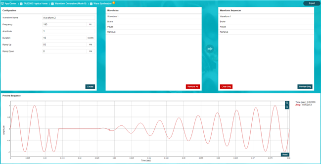
The first consideration to keep in mind when designing your haptic system is waveform synthesis. The synthesized waveform that drives the LRA is crucial in creating a high quality haptic response. To help you with quick prototyping and integration of the amplifier into your haptic configuration, our team created a new application in the PurePath™ Console 3 software. Figure 1 is an example from the TAS2560 application that shows a preview of the waveform generation tool. You can use this tool to fine tune your haptic response based on the LRA. Once the waveform is created, you can export the data and load it into the host processor in your system. The TAS2557 application can generate waveforms in the DSP and does not require exporting the data to the host processor.
 Figure 1 TAS2560 Waveform
Synthesizer
Figure 1 TAS2560 Waveform
SynthesizerWaveform Effect
The second consideration for the haptic system is the waveform effect, particularly the frequency and magnitude of the effect. The frequency of the haptic effect will influence the user experience. People perceive low frequencies near 50Hz as a rumble, as opposed to higher frequencies, like 200Hz, which can feel like a crisp buzz. The waveform frequency also affects the rise time of the signal. For example, if you want a waveform to last 10ms and the frequency is 150Hz, you can only drive 1 cycle (equivalent to 1/150Hz or 6.667ms) before applying a half cycle brake signal. An example of a braking signal can be seen in Figure 1 after waveform 1 and before the pause. The brake is applied 180 degrees out of phase from the driving signal and is meant to stop the LRA. After braking, your acceleration profile will be 15-20ms long. If you drove a 200Hz waveform, then you could drive 1.5 cycles and brake for half a cycle for a total waveform time of 10ms. Of course, you need to have an actuator with the respective resonance frequency in order to produce strong acceleration. Short click waveforms are typically <25ms, including the braking portion.
The magnitude of the waveform with previous drivers was limited to the battery voltage. This magnitude can now be boosted up to 8V with TI’s Smart Amp products.
System Delay Time
The third system topic to consider is the overall system delay time. While timing is important in all systems, it’s especially critical for haptics because it’s related to a good user experience. Figure 2 sums up the delay time for most systems. The three major delays come from the touch sensor, application processor and haptic driver. I recommend keeping the sum of all three delay times near or below 50ms for the best user experience. The driver delay time for the TAS2560 Class-D amplifier is 9-11ms, including the I2C transactions and boost startup time. As the delay time grows, you begin to notice a lag in the tactile response with respect to the touch event.
 Figure 2 Signal Delay Path
Actuator Placement
The final system consideration is the placement of the LRA. To optimize the haptic effect when consumers click the soft keys or home button on a smartphone, for example, place the LRA near the bottom of the phone, as shown in Figure 3. LRA placement can become more complicated for wall-mounted designs or tablets with large surfaces. For a wall-mounted application, you’ll need to isolate the surface being touched from the wall mount by using grommets or an isolation layer. You can find an example of an isolated screen design in the Haptic Feedback Capacitive Touch Display Reference Design for Building Automation and Medical Applications. Tablets may require multiple actuators to provide sufficient acceleration across the surface. The actuator placement and waveform effect timing needs to be optimized so that acceleration waves do not cancel each other out.
 Figure 3 LRA Placement in a Smartphone
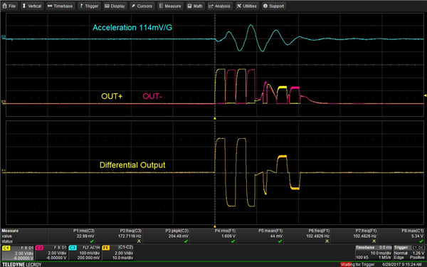
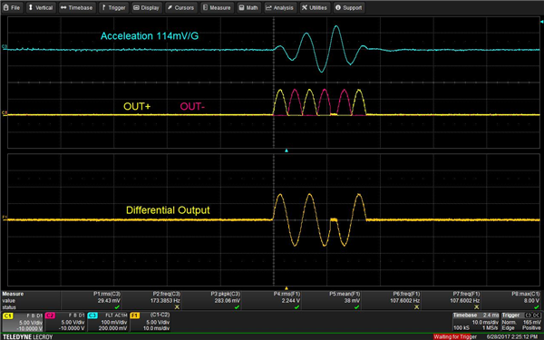
Figure 4 and Figure 5 show the driving of an actuator using a 5.1Vp haptics driver versus the TAS2560 (8Vp) Class-D audio amplifier, respectively. The drive signal is ~10ms for both figures, but the acceleration for the TAS2560 is 2.5G compared to 1.8G for the haptics driver. That is a 32% increase in acceleration.
 Figure 4 Acceleration Profile for the Haptics Driver
 Figure 5 Acceleration Profile for the TAS2560 Class-D Audio Amplifier
There are some significant design considerations before you can start implementing haptics in your design. In your next design, I hope you consider implementing these new LRAs, which are capable of much stronger haptic feedback and can provide a better user experience.
Additional Resources
- Download the TAS2560 and TAS2557 data sheets.
- If you have any questions about haptic design visit the TI E2E™ Community Haptics forum.
IMPORTANT NOTICE AND DISCLAIMER
TI PROVIDES TECHNICAL AND RELIABILITY DATA (INCLUDING DATASHEETS), DESIGN RESOURCES (INCLUDING REFERENCE DESIGNS), APPLICATION OR OTHER DESIGN ADVICE, WEB TOOLS, SAFETY INFORMATION, AND OTHER RESOURCES “AS IS” AND WITH ALL FAULTS, AND DISCLAIMS ALL WARRANTIES, EXPRESS AND IMPLIED, INCLUDING WITHOUT LIMITATION ANY IMPLIED WARRANTIES OF MERCHANTABILITY, FITNESS FOR A PARTICULAR PURPOSE OR NON-INFRINGEMENT OF THIRD PARTY INTELLECTUAL PROPERTY RIGHTS.
These resources are intended for skilled developers designing with TI products. You are solely responsible for (1) selecting the appropriate TI products for your application, (2) designing, validating and testing your application, and (3) ensuring your application meets applicable standards, and any other safety, security, or other requirements. These resources are subject to change without notice. TI grants you permission to use these resources only for development of an application that uses the TI products described in the resource. Other reproduction and display of these resources is prohibited. No license is granted to any other TI intellectual property right or to any third party intellectual property right. TI disclaims responsibility for, and you will fully indemnify TI and its representatives against, any claims, damages, costs, losses, and liabilities arising out of your use of these resources.
TI’s products are provided subject to TI’s Terms of Sale (www.ti.com/legal/termsofsale.html) or other applicable terms available either on ti.com or provided in conjunction with such TI products. TI’s provision of these resources does not expand or otherwise alter TI’s applicable warranties or warranty disclaimers for TI products.
Mailing Address: Texas Instruments, Post Office Box 655303, Dallas, Texas 75265
Copyright © 2023, Texas Instruments Incorporated