-
Powering High-current Broadcom Networking Processors in Ethernet Switches
Powering High-current Broadcom Networking Processors in Ethernet Switches
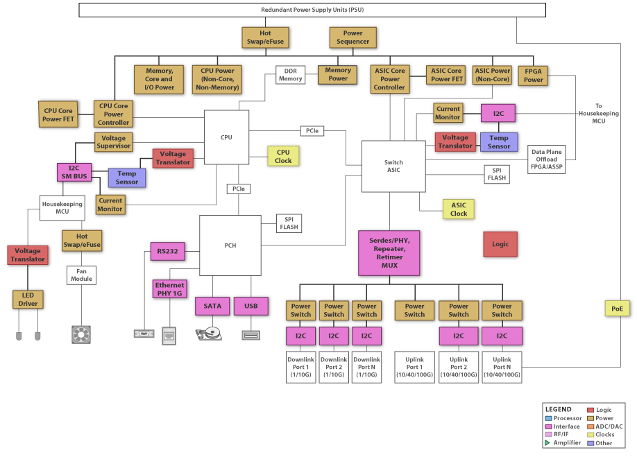
Broadcom networking processors such as the StrataXGS Tomahawk family enable high density and performance in Ethernet switches (Figure 1 is a block diagram of an Ethernet switch; the switch ASIC could be the StrataXGS processor).
 Figure 1 Ethernet Switch
These processors require high current at low voltages, so their associated power solutions must provide tight load regulation, high power density, excellent thermal performance and fast load-transient response. Multiphase buck regulators power the core rail. Multiphase buck DC/DC design requires operating several buck stages in a staggered fashion out of phase.
The TPS53681 6+2 PMBus buck pulse-width modulation (PWM) controller works with the CSD95490 power stages to meet StrataXGS requirements. This driverless PWM architecture uses the TPS53681 controller and power stages. The power stages combine a high-current metal-oxide semiconductor field-effect transistor (MOSFET) gate driver and a high- and low-side MOSFET in one package. TI’s proprietary PowerStack™ package enables easy printed circuit board (PCB) layout, simplified heatsinking and better overall thermal management.
This driverless PWM + power stage approach also enables higher switching frequencies, higher power density and lower noise compared to controllers with integrated MOSFET gate drivers and external MOSFETs.
With the dual-output configuration, you can power both the core rail and a secondary rail from a single chip: six phases for the core rail, two phases for the secondary rail. Additionally, the TPS53681 has a PMBus interface that enables you to set the power-supply functions via registers on-chip, reducing the external component count. You can fully customize parameters such as output voltage/margining, current limit, soft start and transition rate between voltage steps, as well as monitoring of input and output voltage, current, power, and temperature.
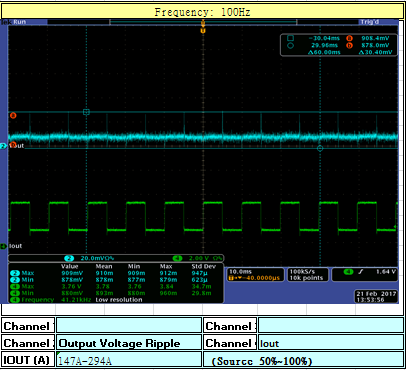
The TPS53681 enables fast load-transient response due to its DCAP+™ control mode, as shown in Figure 2.
 Figure 2 TPS53681 Load Transient
Response, 147A to 294A Load
Figure 2 TPS53681 Load Transient
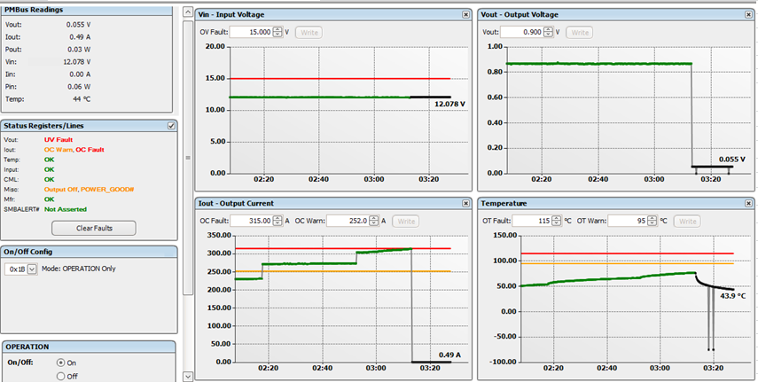
Response, 147A to 294A LoadThe TPS53681 offers latch-off overcurrent protection (shutting the device off upon the detection of overcurrent) to protect the StrataXGS processor. When the output current encounters an overcurrent warning and limit PMBus flags are set, the output current and voltage will shut down, as shown in Figure 3.
 Figure 3 Output Current Overcurrent
Response – Warning at 252A, Latch off at 315A
Figure 3 Output Current Overcurrent
Response – Warning at 252A, Latch off at 315AThe TPS53681 and CSD95490 six-phase buck design can achieve >87% efficiency at 300A of load current, as shown in Figure 4.
 Figure 4 TPS53681 Design Efficiency:
12V Input, <1V/300A Output
Figure 4 TPS53681 Design Efficiency:
12V Input, <1V/300A OutputTI’s Fusion Digital Power Designer™ graphical user interface (GUI) can monitor the power-supply temperature, as well as the input voltage, input current and output current via PMBus, as shown in Figure 5.
 Figure 5 PMBus Monitoring of the
TPS53681’S Input Voltage, Input Current, Output Current and Temperature
Figure 5 PMBus Monitoring of the
TPS53681’S Input Voltage, Input Current, Output Current and TemperatureIf you are designing with Broadcom’s StrataXGS processors for Ethernet switches, the TPS53681 6+2 controller and CSD95490 power stages enable a high-performance, high-power-density design with full capabilities of customization and system monitoring.
Additional Resources
- For more details about multiphase buck DC/DC design, download the application report, “Multiphase Buck Design from Start to Finish.”
- Review TI’s PMBus controller power portfolio on the digital power portal.
IMPORTANT NOTICE AND DISCLAIMER
TI PROVIDES TECHNICAL AND RELIABILITY DATA (INCLUDING DATASHEETS), DESIGN RESOURCES (INCLUDING REFERENCE DESIGNS), APPLICATION OR OTHER DESIGN ADVICE, WEB TOOLS, SAFETY INFORMATION, AND OTHER RESOURCES “AS IS” AND WITH ALL FAULTS, AND DISCLAIMS ALL WARRANTIES, EXPRESS AND IMPLIED, INCLUDING WITHOUT LIMITATION ANY IMPLIED WARRANTIES OF MERCHANTABILITY, FITNESS FOR A PARTICULAR PURPOSE OR NON-INFRINGEMENT OF THIRD PARTY INTELLECTUAL PROPERTY RIGHTS.
These resources are intended for skilled developers designing with TI products. You are solely responsible for (1) selecting the appropriate TI products for your application, (2) designing, validating and testing your application, and (3) ensuring your application meets applicable standards, and any other safety, security, or other requirements. These resources are subject to change without notice. TI grants you permission to use these resources only for development of an application that uses the TI products described in the resource. Other reproduction and display of these resources is prohibited. No license is granted to any other TI intellectual property right or to any third party intellectual property right. TI disclaims responsibility for, and you will fully indemnify TI and its representatives against, any claims, damages, costs, losses, and liabilities arising out of your use of these resources.
TI’s products are provided subject to TI’s Terms of Sale (www.ti.com/legal/termsofsale.html) or other applicable terms available either on ti.com or provided in conjunction with such TI products. TI’s provision of these resources does not expand or otherwise alter TI’s applicable warranties or warranty disclaimers for TI products.
Mailing Address: Texas Instruments, Post Office Box 655303, Dallas, Texas 75265
Copyright © 2023, Texas Instruments Incorporated