-
When Should You Use PWM Controllers?
When Should You Use PWM Controllers?
Brian Johnson96

PWM is a control method that can be applied to many power-supply topologies. And because power supplies, regardless of topology, are used in an endless set of applications, they have the reputation of being used everywhere; PWMs are used in a wide variety of applications.
PWM is short for pulse-width modulation. In the context of a switched-mode power supply, PWM is the scheme used to regulate an output such as an output voltage and reject variation from the input voltage to a system. This system concept describes a switched-mode power supply. The inputs and outputs can be DC, sinusoidal (AC) or even some other periodic waveform.
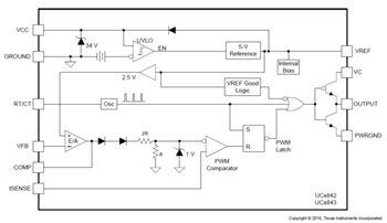
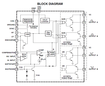
Consider two very popular PWM controller families, the UC3842/UC3843/UC3844/UC3845 (UCx84x) and the UC1525A/UC2525A/UC3525A/UC3846 (UCx525A). Figure 1 and Figure 2 show these families’ block diagrams, respectively.
 Figure 1 UCx84x Block Diagram
 Figure 2 UCx525A Block Diagram
Both figures highlight a common PWM control method, where an error signal compared to a fixed-frequency ramp produces a PWM output that drives the switches in a switched-mode power-supply topology. The error signal can control current, voltage, both current and voltage, or some other significant property in the end application. The topology can involve a single switch, as found in buck, boost, flyback or forward topologies; the UCx84x is a good PWM controller to consider for these types of topologies. Consider the Ucx525A for topologies (excluding synchronous rectification) that have more than two switches, like the Fly-Buck™ converter, active clamp forward, push-pull or half bridge. At times, a MOSFET gate driver is needed in order to drive the MOSFET. These two families of PWMs are very basic controllers, with uncomplicated logic and just the right amount of extra features, making them easy to implement in many applications.
Applications with PWMs include welding, appliances, motor drives, personal electronics, inverters, electric vehicles, uninterruptable power supplies, solar power, audio amplifiers and car heaters. In general, where switched-mode power supplies are used and you don’t need the complexities of a more advanced topology, think about using a simple generic PWM controller.
Using your favorite PWM controller in many applications can decrease development time while you build power-supply design confidence with a set of proven designs tucked up your sleeve. One final advantage in using a PWM is that it can be leveraged across multiple designs, keeping your procurement team excited about a high-volume sourced component.
Improvements in the process technology used to manufacture the generic purpose PWM controllers from a bipolar technology to a current Bi-CMOS technology can improve critical design parameters. A quick comparison between the UC284X/UC384X and the UCC28C4X/UCC38C4X details improvements due to the process change on a controller architecture that has remained the same: lower supply current from 11 mA to 2.3 mA at 50 kHz, rise/fall times from 50 ns to 25 ns and reference voltage accuracy from ±2 % to ±1 %. Even the operating frequency is increased from 500 kHz to > 1 MHx to name a few areas of improvement.
Visit our PWM and resonant controller overview page to see other PWM controllers and explore application and design ideas. You can also start a design in WEBENCH high voltage designer with TI’s high performance, current mode PWM controllers.
Additional Resources
- PWM design concepts have been explored in-depth since the beginning of the TI Power Supply Design Seminar, proving that PWM is a workhorse for the power-supply industry. Read Bob Mammano’s paper, “Switching Power Supply Topology Voltage Mode vs. Current Mode.”
- Read our Power Topologies Quick Reference Guide.
- Get to know TI’s MOSFET and IGBT Gate drivers.
IMPORTANT NOTICE AND DISCLAIMER
TI PROVIDES TECHNICAL AND RELIABILITY DATA (INCLUDING DATASHEETS), DESIGN RESOURCES (INCLUDING REFERENCE DESIGNS), APPLICATION OR OTHER DESIGN ADVICE, WEB TOOLS, SAFETY INFORMATION, AND OTHER RESOURCES “AS IS” AND WITH ALL FAULTS, AND DISCLAIMS ALL WARRANTIES, EXPRESS AND IMPLIED, INCLUDING WITHOUT LIMITATION ANY IMPLIED WARRANTIES OF MERCHANTABILITY, FITNESS FOR A PARTICULAR PURPOSE OR NON-INFRINGEMENT OF THIRD PARTY INTELLECTUAL PROPERTY RIGHTS.
These resources are intended for skilled developers designing with TI products. You are solely responsible for (1) selecting the appropriate TI products for your application, (2) designing, validating and testing your application, and (3) ensuring your application meets applicable standards, and any other safety, security, or other requirements. These resources are subject to change without notice. TI grants you permission to use these resources only for development of an application that uses the TI products described in the resource. Other reproduction and display of these resources is prohibited. No license is granted to any other TI intellectual property right or to any third party intellectual property right. TI disclaims responsibility for, and you will fully indemnify TI and its representatives against, any claims, damages, costs, losses, and liabilities arising out of your use of these resources.
TI’s products are provided subject to TI’s Terms of Sale (www.ti.com/legal/termsofsale.html) or other applicable terms available either on ti.com or provided in conjunction with such TI products. TI’s provision of these resources does not expand or otherwise alter TI’s applicable warranties or warranty disclaimers for TI products.
Mailing Address: Texas Instruments, Post Office Box 655303, Dallas, Texas 75265
Copyright © 2023, Texas Instruments Incorporated