-
Engineering Magic: Touch through Thick Glass with LEDs and LCD
Engineering Magic: Touch through Thick Glass with LEDs and LCD
Giovanni Campanella
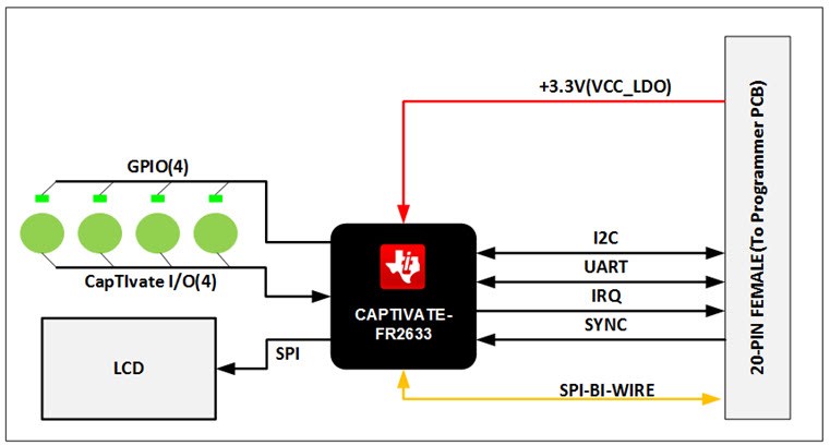
Not impressed with the magic trick revealed in the previous post? Then check out this one: We kept working on our touch-through-glass application and managed to improve it. Using an MSP430™ microcontroller (MCU) with CapTIvate™ technology (the MSP430FR2633), we were able to control light-emitting diodes (LEDs) and a liquid crystal display (LCD) upon button presses, beyond just sensing the buttons as we did with the Low-Power Touch Through Glass Reference Design (TIDA-00343). Figure 1 is a block diagram of the Touch Through Glass with LCD Reference Design (TIDA-00494).
 Figure 1 Block diagram for the LCD
reference design (TIDA-00494)
Figure 1 Block diagram for the LCD
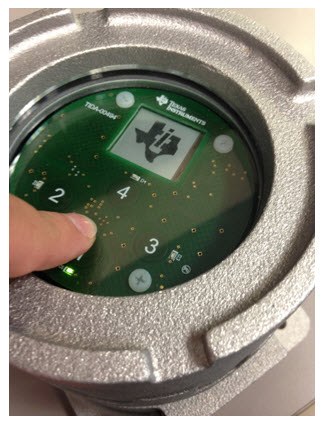
reference design (TIDA-00494)If you’ll recall from my previous post, process plant operators need to interact daily with a keypad for programming functions. The keypad is encapsulated in an explosive-proof screw-on metallic enclosure with thick glass windows, with local readouts through an LCD (see Figure 2).
 Figure 2 TIDA-00494 Touch through Glass
reference design
Figure 2 TIDA-00494 Touch through Glass
reference designFactory automation and process control designers struggle to find ways for operators to interact with these explosion-proof field transmitters without having to open the enclosures, which can be time-consuming.
Let’s think about already existing technologies that could solve this issue:
- Infrared technology detects button presses through light changes when a finger approaches the sensor. However, this technology is unreliable in industrial environments. If the glass is caked with oil or dust, a spot on the button area could cause a false touch detection.
- A magnetic solution would entail having a magnetic switch, which closes when it detects a strong magnetic field nearby. But the user would have to have a magnetic pen on hand at all times to generate the magnetic field.
Capacitive technology solves these problems; in addition, the number of buttons does not affect the cost of the application, since adding buttons means adding only extra copper to the PCB.
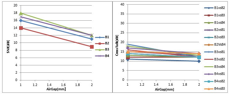
We have proved the robustness of CapTIvate™ technology by performing many tests, including touch with bare fingers and touch with gloves. We have also tried to recreate false-touch situations. In each test, we took 1,000 samples while pressing a button and 1,000 samples without performing any action. Then we calculated the mean and standard deviation of each event to estimate the signal-to-noise ratio (SNR) and crosstalk among the buttons.
To ensure that the probability of a button being touched is equal to 99.73%, the SNR must be greater than 9.5dB. To ensure that a button press does not influence the nearby button, the crosstalk should be as well greater than 9.5dB. The test results meet this threshold; see Figure 3.
 Figure 3 Touch & crosstalk
tests
Figure 3 Touch & crosstalk
testsCapacitive technology has its own limitations (which I mentioned in my previous post) related to the air gap needed between the glass and the PCB, which should be as small as possible.
The reference design can detect a touch event with or without gloves, even though the electrode board has an air gap of as much as 2mm from the 10mm-thick glass and gives feedback through LEDs and an LCD with only one chip.
Additional Resources:
- Check out High-Temperature Touch through Glass Reference Design (TIDA-00464).
- Read “Capacitive touch in industrial HMI” blog post on Industrial Strength.
- Order a Sharp Memory LCD BoosterPack plug-in module.
- Find out more about factory automation and process control.
- Watch our demo video to see the reference design in action:
IMPORTANT NOTICE AND DISCLAIMER
TI PROVIDES TECHNICAL AND RELIABILITY DATA (INCLUDING DATASHEETS), DESIGN RESOURCES (INCLUDING REFERENCE DESIGNS), APPLICATION OR OTHER DESIGN ADVICE, WEB TOOLS, SAFETY INFORMATION, AND OTHER RESOURCES “AS IS” AND WITH ALL FAULTS, AND DISCLAIMS ALL WARRANTIES, EXPRESS AND IMPLIED, INCLUDING WITHOUT LIMITATION ANY IMPLIED WARRANTIES OF MERCHANTABILITY, FITNESS FOR A PARTICULAR PURPOSE OR NON-INFRINGEMENT OF THIRD PARTY INTELLECTUAL PROPERTY RIGHTS.
These resources are intended for skilled developers designing with TI products. You are solely responsible for (1) selecting the appropriate TI products for your application, (2) designing, validating and testing your application, and (3) ensuring your application meets applicable standards, and any other safety, security, or other requirements. These resources are subject to change without notice. TI grants you permission to use these resources only for development of an application that uses the TI products described in the resource. Other reproduction and display of these resources is prohibited. No license is granted to any other TI intellectual property right or to any third party intellectual property right. TI disclaims responsibility for, and you will fully indemnify TI and its representatives against, any claims, damages, costs, losses, and liabilities arising out of your use of these resources.
TI’s products are provided subject to TI’s Terms of Sale (www.ti.com/legal/termsofsale.html) or other applicable terms available either on ti.com or provided in conjunction with such TI products. TI’s provision of these resources does not expand or otherwise alter TI’s applicable warranties or warranty disclaimers for TI products.
Mailing Address: Texas Instruments, Post Office Box 655303, Dallas, Texas 75265
Copyright © 2023, Texas Instruments Incorporated