Click! Clack! What’s the Setback in Your Thermostat?
Ever wonder what happens when you turn your thermostat on or off? You hear clicking sounds, but you may not actually know what is happening. A simple answer would be that the thermostat switch sends a control signal to the system in charge of maintaining a desired room temperature. But how?
Within heating, ventilation and air conditioning (HVAC) systems are devices that regulate heating and cooling systems according to the thermostat’s input control signal. Electromechanical relays typically provide the control signal to the HVAC system following the input set by the user. An example of a thermostat user interface is shown in Figure 1.
 Figure 1 Thermostat with a Digital User
Interface
Figure 1 Thermostat with a Digital User
InterfaceA basic thermostat for heating and cooling uses four or five wires to control the HVAC system, as shown in Figure 1. The white (W), green (G) and yellow (Y) wires connect to the heating, air flow and cooling systems, respectively. In Figure 2, the red cooling and heating (Rc and Rh) wires are connected to create a four-wire system when both cooling and heating systems are combined and connected to a single 24V alternating current (AC) transformer.
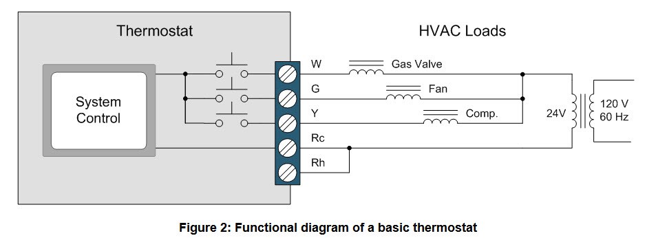
Separate heating and cooling systems will use separate 24V AC transformers. In such cases, the Rc wire connects to the transformer in the cooling system and the Rh wire connects to the transformer in the heating system. Basic thermostats for single- or dual-transformer systems use three electromechanical relays, one for each of the W, G and Y wires. In higher-end heating and cooling systems with multistage compressors, fans and heat pumps, the thermostat can have as many as 10 electromechanical relays. These extra relays are used for more sophisticated system algorithms, to control additional heating/cooling stages, heat pumps, auxiliary heat, humidifiers and dehumidifiers.
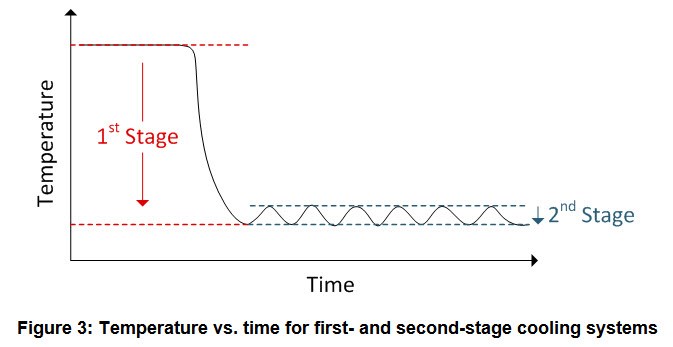
Multistage heating/cooling systems minimize ambient temperature variation while maximizing energy efficiency. Such systems comprise different-sized devices. One example of a multistage cooling system is one with two compressors. The main compressor is generally in the range of 6T, while the second stage is much smaller, in the range of 2T. The 6T compressor handles large drops in temperature in a short period of time, as shown in Figure 3. For example, when you come home from work and want the temperature to quickly drop to your desired level, that’s the first stage. The second stage consists of a more energy-efficient 2T compressor which maintains the desired temperature once the HVAC system achieves that level.
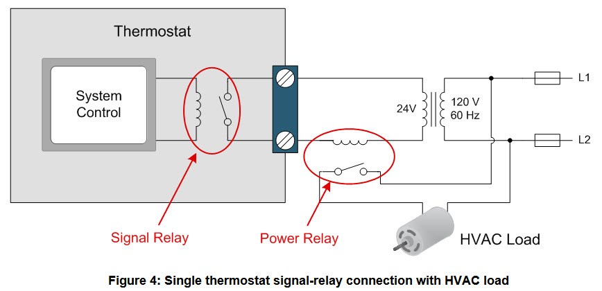
Now that you have a better understanding of what the HVAC system controls, let’s focus on the thermostat’s on/off control – and that funny clicking sound you hear. In Figure 4, you can see the signal relay in the thermostat. This relay is connected in series with a 24V AC transformer and a power relay within the HVAC system. The power relay enables and disables devices like fan motors, compressors or gas valves.
When the signal relay closes, the current from the 24V AC transformer flows through the contactor coil of the power relay, activating its mechanical contact. When the signal relay opens, the current is interrupted and the contact of the power relay deactivates. Thus, the closed contact of the power relay enables the connection between the 120V AC of the HVAC system and the motor(s) using a low-voltage signal relay.
HVAC load control traditionally uses electromechanical relays for two reasons. First, the on-resistance of an electromechanical relay is low, which eliminates the need for a heat sink. And second, the functionality of the relay allows the same device (up to its maximum voltage and current ratings) to control both AC and DC loads.
Unfortunately, the mechanical contacts are not always ideal. One disadvantage is that a clicking sound occurs every time the movable contact connects with the fixed contact during activation and deactivation of the electromechanical relay. This is the clicking sound you hear when the thermostat enables or disables the HVAC system and it can be rather annoying. A second disadvantage is that these contacts will eventually fail and limit the life of your thermostat.
Even with proper relay design of an electromechanical relay, the probability of failure increases further in HVAC systems due to the current interruption of the inductive loads. The interruption of current leads to a voltage spike and will damage the mechanical contact over time. The relay contacts also have a tendency to bounce, spark and have longer turn-on/turn-off times, which make them rather unsuitable for today’s smart thermostats.
Fortunately, there is a solution that eliminates the negative characteristics of the electromechanical relay: a device called a solid-state relay (SSR). An SSR uses thyristors and power transistors to perform on/off control with a low-voltage or current input.
For more information on SSRs, stay tuned for the next blog providing an overview and further benefits of this innovative approach.
Additional Resources
- Check out the Solid State Relay 24V AC Switch with Galvanic Isolation Reference Design (TIDA-00751)
- Learn more about thermostats with this professional reference guide from Ritetemp Thermostats
- Find more design resources on the thermostat solutions page.
IMPORTANT NOTICE AND DISCLAIMER
TI PROVIDES TECHNICAL AND RELIABILITY DATA (INCLUDING DATASHEETS), DESIGN RESOURCES (INCLUDING REFERENCE DESIGNS), APPLICATION OR OTHER DESIGN ADVICE, WEB TOOLS, SAFETY INFORMATION, AND OTHER RESOURCES “AS IS” AND WITH ALL FAULTS, AND DISCLAIMS ALL WARRANTIES, EXPRESS AND IMPLIED, INCLUDING WITHOUT LIMITATION ANY IMPLIED WARRANTIES OF MERCHANTABILITY, FITNESS FOR A PARTICULAR PURPOSE OR NON-INFRINGEMENT OF THIRD PARTY INTELLECTUAL PROPERTY RIGHTS.
These resources are intended for skilled developers designing with TI products. You are solely responsible for (1) selecting the appropriate TI products for your application, (2) designing, validating and testing your application, and (3) ensuring your application meets applicable standards, and any other safety, security, or other requirements. These resources are subject to change without notice. TI grants you permission to use these resources only for development of an application that uses the TI products described in the resource. Other reproduction and display of these resources is prohibited. No license is granted to any other TI intellectual property right or to any third party intellectual property right. TI disclaims responsibility for, and you will fully indemnify TI and its representatives against, any claims, damages, costs, losses, and liabilities arising out of your use of these resources.
TI’s products are provided subject to TI’s Terms of Sale (www.ti.com/legal/termsofsale.html) or other applicable terms available either on ti.com or provided in conjunction with such TI products. TI’s provision of these resources does not expand or otherwise alter TI’s applicable warranties or warranty disclaimers for TI products.
Mailing Address: Texas Instruments, Post Office Box 655303, Dallas, Texas 75265
Copyright © 2023, Texas Instruments Incorporated
