How to Detect Insulation Failures in Electrical Equipment – Part 2
In my last post, I emphasized the importance of insulation in electrical equipment. In this post, I will describe another method to measure the leakage current through the insulation resistance.
Figure 1 is a high-level block diagram of this method, which entails applying a fixed voltage (500V, generated using a high-voltage DC/DC converter on a daughter board) and measuring the voltage across the shunt that results from the leakage current. Multiple, switchable shunt resistances switch on in a sequence to measure the insulation resistance.

When there is a dead short, the insulation resistance is 0Ω, and a full or maximum current (equal to 500V/RLIMIT) can pass through the insulation resistance. At this point in the measurement, having a smaller shunt value (by turning all of the switches on) is mandatory. This approach is called a “single-shunt” approach. Higher insulation requires a higher shunt value, achieved by turning the MOSFET switches on and off. This approach is called a “multiple-shunt” approach. A current-shunt monitor (CSM) measures the leakage current flowing through the shunt(s). If required, you can use the gain-setting pins of the CSM to amplify the leakage current with gain. If gain is not required, use a multiplexer (MUX) to directly route the voltage across the shunt.
Since the measurement circuit is connected to high voltage, an isolated amplifier (ISO AMP) isolates the measured output voltage; you can connect the ISO AMP output to an MCU (Microcontroller). MCU also generates signals to control the switchable shunts, gain settings for CSM and MUX channels; a digital isolator isolates these signals.
Figure 2 shows a single-shunt approach in which the MOSFET switches are off, the CSM’s GS0 and GS1 pins gain the measured current, and the MUX is programmed to select the CSM output.
Figure 3 shows a multiple-shunt approach in which the MOSFET switches turn on and off based on the measured signal, a CSM is not used, and MUX is programmed to select the voltage across the shunt directly.


I tested this method for measurement accuracy with both of the approaches illustrated in Figures 2 and 3.
Figure 4 shows the measurement accuracy for a single-shunt approach. The shunt-resistor value is fixed at 22Ω, but you can vary the gain of the CSM (the INA225 in this case) on the fly. The two colors specify the gain settings (gain = 25 V/V for the yellow section and gain = 200 V/V for the brown section).

Figure 5 shows the measurement accuracy for a multiple-shunt approach. The MOSFETs turning on and off dynamically change the shunt-resistor value, while the output of the ISO AMP must not go below 200mV at any time. For an insulation resistance between 0Ω and 3MΩ, the value of the shunt resistor is 220kΩ || 2.7kΩ || 261Ω (the green area). For an insulation resistance between 3.1MΩ and 39.6MΩ, the value of the shunt resistor is 220 kΩ || 2.7kΩ (the pink area). For an insulation resistance between 39.7MΩ and 98.4MΩ, the value of the shunt resistor is 220kΩ (the blue area).

I tested the proposed method with a motor, as shown in Figure 6. I took the insulation-resistance measurement between one of the motor terminals (the yellow wire) and the frame of the motor (the black wire). Figure 7 shows a zoomed-in version of the motor section. For this experiment I used a 2HP three-phase AC induction motor.
The insulation resistance of the motor (measured with high-resistance measuring equipment from Keithley) was 547MΩ. For the sake of measurement, I purposely created an insulation failure by connecting one 100MΩ resistance in parallel with the motor insulation. The insulation resistance was 547MΩ || 100MΩ = 84.54MΩ (theoretically). I measured the parallel combination with this method.

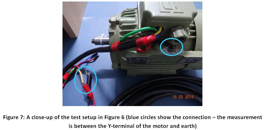
Table 1 shows the measured values of insulation resistance with both the single- and multiple-shunt approaches.

Insulation measurement is an essential part of diagnostics and testing for any electrical equipment. In factories, such measurements help customers reduce or prevent downtime caused by such failures. Accuracies for insulation measurement tests may not be mandatory, as the range of insulation resistance is enough to guess the condition of failure. But the method I’ve described here has measurement error less than 5%.
Additional Resources
- View the technical documents for the TI Designs Leakage Current Measurement Reference Design for Determining Insulation Resistance.
- View the IEEE standard
- See Part 1 of How to detect insulation failures in electrical equipment
IMPORTANT NOTICE AND DISCLAIMER
TI PROVIDES TECHNICAL AND RELIABILITY DATA (INCLUDING DATASHEETS), DESIGN RESOURCES (INCLUDING REFERENCE DESIGNS), APPLICATION OR OTHER DESIGN ADVICE, WEB TOOLS, SAFETY INFORMATION, AND OTHER RESOURCES “AS IS” AND WITH ALL FAULTS, AND DISCLAIMS ALL WARRANTIES, EXPRESS AND IMPLIED, INCLUDING WITHOUT LIMITATION ANY IMPLIED WARRANTIES OF MERCHANTABILITY, FITNESS FOR A PARTICULAR PURPOSE OR NON-INFRINGEMENT OF THIRD PARTY INTELLECTUAL PROPERTY RIGHTS.
These resources are intended for skilled developers designing with TI products. You are solely responsible for (1) selecting the appropriate TI products for your application, (2) designing, validating and testing your application, and (3) ensuring your application meets applicable standards, and any other safety, security, or other requirements. These resources are subject to change without notice. TI grants you permission to use these resources only for development of an application that uses the TI products described in the resource. Other reproduction and display of these resources is prohibited. No license is granted to any other TI intellectual property right or to any third party intellectual property right. TI disclaims responsibility for, and you will fully indemnify TI and its representatives against, any claims, damages, costs, losses, and liabilities arising out of your use of these resources.
TI’s products are provided subject to TI’s Terms of Sale (www.ti.com/legal/termsofsale.html) or other applicable terms available either on ti.com or provided in conjunction with such TI products. TI’s provision of these resources does not expand or otherwise alter TI’s applicable warranties or warranty disclaimers for TI products.
Mailing Address: Texas Instruments, Post Office Box 655303, Dallas, Texas 75265
Copyright © 2023, Texas Instruments Incorporated
