-
How to Select the Right Industrial Ethernet Standard: PROFINET
How to Select the Right Industrial Ethernet Standard: PROFINET
Thomas Mauer
This is the third installment of “How to select the right industrial Ethernet standard,” a blog series for designers who have decided to leverage industrial Ethernet in their systems. This series is covering several common industrial Ethernet communication protocols to help you select the right standard for your application. In my previous posts, I discussed EtherCAT and Sercos III.
This time, I’ll look at process field network (PROFINET), one of the leading industrial Ethernet standards for factory automation. There are different versions of PROFINET, and in this post I will be describing PROFINET I/O.
PROFINET network technology is found in factory automation, process automation, building automation, automobile manufacturing lines, power plants and robotics.
PROFINET is the successor to PROFIBUS DP (12Mb serial fieldbus communication over RS-485 transceivers), which originated at Siemens. PROFINET operates on full-duplex 100Mbps Ethernet.
The German-based PROFBUS Nutzerorganisation (PNO) and British-based PROFINET International (PI) maintain the PROFINET standard. The combined organization has more than 1,400 member companies and 70 working groups; these groups define different aspects of industrial fieldbus and industrial Ethernet standards. In 2003, the PROFINET standard became part of the International Electrotechnical Commission (IEC) standards, and is included in IEC 61158 and IEC 61784.
PROFINET has a master-and-slave network architecture, as shown in Figure 1. It consists of an PROFINET input output (I/O) controller that takes over the master role in the network; I/O devices take over the slave roles. PROFINET is very flexible in terms of network topology and includes line topology, ring topology, star topology, and combinations of these using hub and switch devices.
 Figure 1 PROFINET Network in an
Automation System
Figure 1 PROFINET Network in an
Automation SystemImage courtesy PROFIBUS International
Over the years, the PROFINET standard has evolved based on market requirements. Various kinds of performance classes are simply named A, B and C. Each of the performance classes adds more performance functions than the class below it. This approach allows PROFINET to be backward-compatible with previous generations of PROFINET devices.
Let’s list the important functions of each performance class:
- Conformance class A (CC-A):
- Real-time Ethernet communication.
- Cyclic I/O.
- Parameter configuration.
- Alarms.
This is the first version of PROFINET IO, with a cycle time in the 10ms range. In most cases this performance class is implemented on a standard Ethernet media access controller (MAC). The device does not even need to have two Ethernet ports; a single MAC is sufficient.
- Conformance class-B (CC-B).
Same functions as CC-A, plus:
- Network diagnostics.
- Topology detection.
- System redundancy.
This version of PROFINET IO also performs with a cycle time in the 1ms range. A dedicated two-port industrial Ethernet MAC is beneficial (but not a must) for any industrial application in order to reduce frame jitter and cycle-time accuracy.
- Conformance class-C (CC-C):
same functions as CC-B, plus:
- Reserved bandwidth for specific PROFINET frames, also known as isochronous real time (IRT).
- Time synchronization for controller and devices.
This version of PROFINET IO supports a cycle time down to 31.25µs. However, most of the applications are OK with a cycle time of 250µs or slower. The IRT version of PROFINET IO requires a dedicated two-port industrial Ethernet MAC. Therefore, any solution has to be built with dedicated industrial Ethernet MAC hardware, which adds an external field programmable gate array (FPGA) or application specific integrated circuit (ASIC) device. If you are interested in a single-chip solution, check out the Sitara™ processors supporting PROFINET IRT.
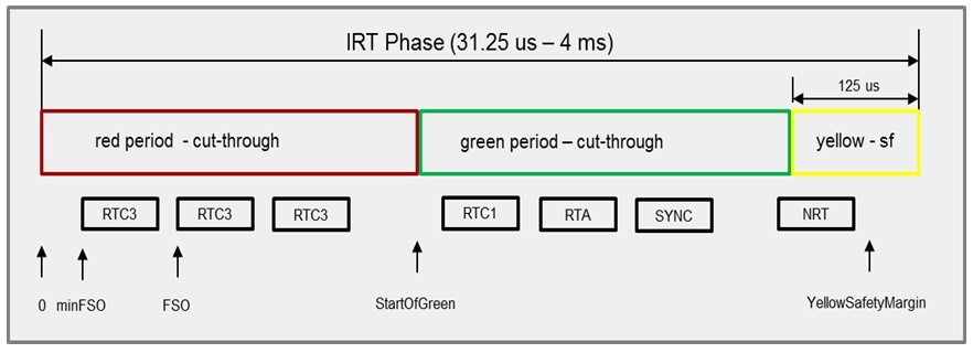
Let’s have a more detailed look at PROFINET IRT. The cycle time splits up into red, green and yellow phases: see Figure 2. Each phase reserves bandwidth for specific types of PROFINET frames and other Ethernet frames.
 Figure 2 PROFINET IRT Communication
Phase
Figure 2 PROFINET IRT Communication
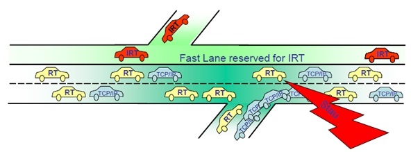
PhaseThe red period is strictly reserved for PROFINET real-time class 3 frames (RTC3), which have the highest priority on any PROFINET network (see Figure 3). Network devices cannot send any other kind of frame during the red phase. Every RTC3 packet is pre-engineered – meaning that the I/O devices send the RTC3 frames at a pre-defined transmission time. These start times are pre-set by the I/O controller in each I/O device during the initial network configuration.
 Figure 3 Profinet Irt Fast Lane
Image courtesy PROFIBUS International
The green period is for all other Ethernet frames, including for PROFINET frames of real-time class 1 (RTC1), PROFINET alarm frames (PTA), time-synchronization frames, PROFINET-related protocol frames and standard transmission control protocol and internet protocol TCP/IP frames.
Network devices cannot start any new frame transmission once the yellow period starts. Frames that started at the end of the green period can finish before the yellow period expires. Those frames do not go into the red phase, as the yellow phase is wide enough to finish the transmission of those frames.
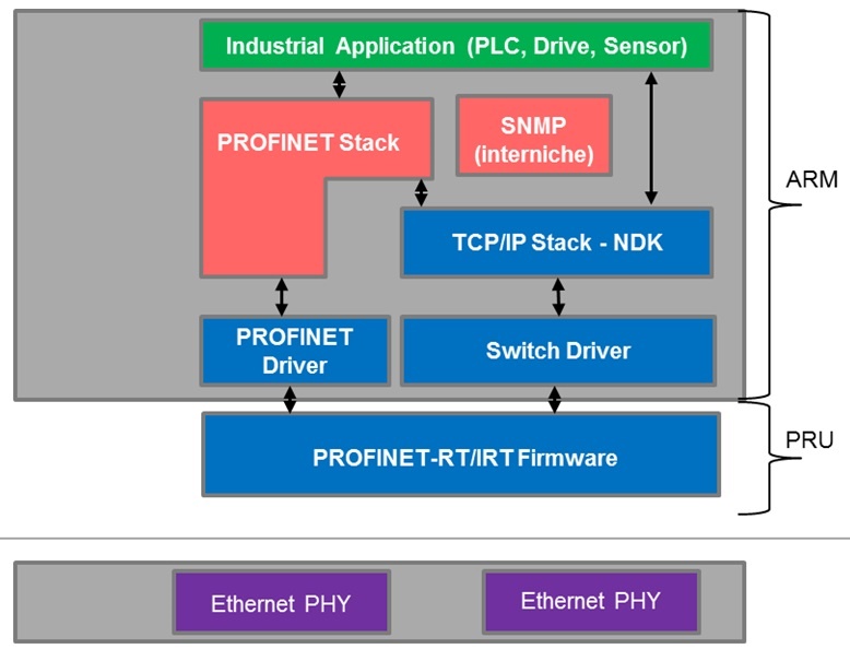
The TI Sitara™ processor solution (see Figure 4) for PROFINET RT and IRT supports all conformance classes, with its very unique programmable real-time unit in the industrial communication subsystem (PRU-ICSS) peripheral. The PRU-ICSS integrates a cut-through switch to handle RTC3 frames during the red phase, as well as all other Ethernet frames in the green and yellow phases. To learn more about the certified PROFINET RT and IRT solutions, see the PROFINET Communications Development Platform (TIDEP0008) and Certified Profinet IRT V2.3 Device with 1 GHZ ARM Application Processor Reference Design (TIDEP0029).
 Figure 4 PROFINET RT/IRT Solution on
Sitara Processors
Figure 4 PROFINET RT/IRT Solution on
Sitara ProcessorsAt this year’s SPS IPC Drives 2015 trade show, coming November 24-26 to Nuremberg, Germany, TI will demonstrate a scalable PROFINET IRT solution across Sitara processors that I think you will enjoy. TI will have a booth in Hall 6, booth No. 441, with an additional presence in the PNO/PI booth in Hall 2, booth No. 220. If you visit the trade show because of this blog, please come find me at TI’s booth to say hello!
I hope this post has shed some light into PROFINET’s functionality. Make sure to read additional posts in this series to learn more about the many industrial Ethernet standards.
Additional Resources
- View the Certified Profinet IRT V2.3 Device with 1 GHz ARM Application Processor Reference Design.
- Read the white paper, “PROFINET on TI’s Sitara processors,” which provides an introduction to this standard.
- Learn more about the PROFINET standard on the PI website.