Power Tips: How to Manage an Ultrawide-input Low-power Flyback
MatthiasUlmann
A wide variety of supply voltages exist in industrial applications and factory automation. Typically, you’ll find 24VAC, 24VDC, 110VAC, 230VAC and sometimes voltages in-between. Electronic device manufacturers usually don’t like to develop different power supplies for each input voltage because of cost. So let’s look at how to design a low-power flyback converter in the 500mW range with an ultrawide input-voltage range of 19 to 265VAC and 19 to375VDC.
The low power flyback reference design, which I will use as an example in this blog, needs to provide two outputs. One output rail supplies a microcontroller and analog circuitry (5.0V at 15mA); the second rail provides 12.0V at 40mA to control a relay. Because the input and two outputs require an isolation of 2.5kV, the simple and well-known flyback converter comes to mind first.
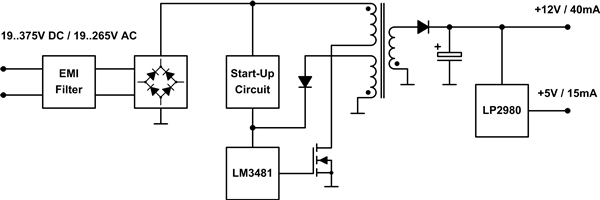
Figure 1 shows the converter including input filter, rectifier, startup circuit and controller linear regulator on the secondary side.
 Figure 1 Flyback converter block
diagram
Figure 1 Flyback converter block
diagramThe wide-input voltage range is not only a challenge for the controller, but also for the design of the transformer. A flyback converter is designed to work in discontinuous conduction mode (DCCM) for low-power applications in order to achieve a small solution size because of the lower inductance of the coupled inductor. The peak currents in this operation mode are higher compared to continuous conduction mode (CCM) – but because the power is low, they are still relatively small. For higher power, the flyback converter is typically working in CCM. At first glance DCCM seems to be the right mode for this flyback design, with an output power of roughly 500mW.
The switching frequency should be relatively low to avoid high switching losses at the upper range of the input voltage. In this design, it is set to 130kHz so that the fundamental wave is below the lower limit of 150kHz for electromagnetic interference (EMI) measurements. If the converter is supposed to work only in DCCM, the duty cycle is in a range from 70% down to 4% (turns ratio 3.58: 1,750µH primary inductance). To reduce component stress, you should increase the minimum duty cycle by keeping the turns ratio constant and changing the primary inductance to 4mH. The converter is now running in CCM for low-input voltages and in DCCM for high-input voltages.
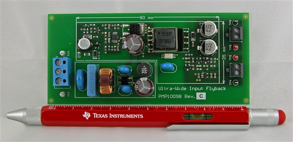
 Figure 2 Low Power Flyback with Ultra
Wide Input Voltage Range TI Designs reference design
Figure 2 Low Power Flyback with Ultra
Wide Input Voltage Range TI Designs reference designIMPORTANT NOTICE AND DISCLAIMER
TI PROVIDES TECHNICAL AND RELIABILITY DATA (INCLUDING DATASHEETS), DESIGN RESOURCES (INCLUDING REFERENCE DESIGNS), APPLICATION OR OTHER DESIGN ADVICE, WEB TOOLS, SAFETY INFORMATION, AND OTHER RESOURCES “AS IS” AND WITH ALL FAULTS, AND DISCLAIMS ALL WARRANTIES, EXPRESS AND IMPLIED, INCLUDING WITHOUT LIMITATION ANY IMPLIED WARRANTIES OF MERCHANTABILITY, FITNESS FOR A PARTICULAR PURPOSE OR NON-INFRINGEMENT OF THIRD PARTY INTELLECTUAL PROPERTY RIGHTS.
These resources are intended for skilled developers designing with TI products. You are solely responsible for (1) selecting the appropriate TI products for your application, (2) designing, validating and testing your application, and (3) ensuring your application meets applicable standards, and any other safety, security, or other requirements. These resources are subject to change without notice. TI grants you permission to use these resources only for development of an application that uses the TI products described in the resource. Other reproduction and display of these resources is prohibited. No license is granted to any other TI intellectual property right or to any third party intellectual property right. TI disclaims responsibility for, and you will fully indemnify TI and its representatives against, any claims, damages, costs, losses, and liabilities arising out of your use of these resources.
TI’s products are provided subject to TI’s Terms of Sale (www.ti.com/legal/termsofsale.html) or other applicable terms available either on ti.com or provided in conjunction with such TI products. TI’s provision of these resources does not expand or otherwise alter TI’s applicable warranties or warranty disclaimers for TI products.
Mailing Address: Texas Instruments, Post Office Box 655303, Dallas, Texas 75265
Copyright © 2023, Texas Instruments Incorporated