-
Identify the Most Accurate Linear Voltage Regulator
Identify the Most Accurate Linear Voltage Regulator
Brett Colteaux

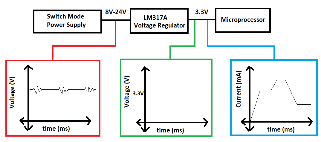
Would you like your microprocessor to have peak performance all the time? Imagine that the power for your microprocessor consists of a switch mode power supply and a linear regulator, which allows for minimum power consumption. The block diagram for this system can be seen below in Figure 1.
 Figure 1 Microprocessor power
supply.
Figure 1 Microprocessor power
supply.Rapid increases and decreases in current are constantly occurring due to varying processing demands from the microprocessor. In addition, voltage ripple and transient voltages at the output of the switched mode power supply causes varying voltages at the input of the linear regulator. Furthermore, the output voltage can change due to deviations in the internal reference voltage of the regulator.
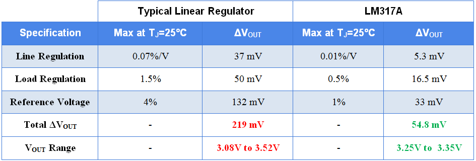
Now, imagine you are using a linear regulator with maximum specification values of line regulation at 0.07%/V, load regulation at 1.5%, and a reference voltage deviation of 4%. The output voltage of this regulator can deviate by as much as 219 mV while TI’s LM317A for example, has output voltage deviation of just 54.8 mV, as shown in Table 1.

|
Note: Conditions used to determine ΔVOUT are 8V ≤ VIN ≤ 24V, 10 mA ≤ IOUT ≤ 1.5A, TJ = 25°C, and VOUT,nominal = 3.3V.
A typical microprocessor desires VCC of 3.3V and maximum VCC of 3.6V. With these specifications taken into consideration, the input voltage of the microprocessor could be up to 3.52V. This leaves only an 80mV margin until the microprocessor stops functioning, which is not enough when considering resistor tolerance values.
The ability to accurately maintain an output voltage is extremely important when it comes to voltage regulators. When choosing a linear voltage regulator for a given application, there are three datasheet specifications that must be scrutinized in order ensure output voltage stability: load regulation, line regulation and reference voltage accuracy.
1. Line Regulation
This specification is used to measure how well a voltage regulator is able to maintain a constant output voltage for input voltage changes. The units of line regulation are expressed in %/V and the value represents the output voltage percent change with respect to input voltage changes. The equation for calculating percent line regulation is as follows:

2. Load Regulation
This specification is used to measure how well a voltage regulator is able to maintain a constant output voltage given load changes. Load regulation, which is typically expressed in percent form, is defined by the following equation:

3. Reference Voltage Accuracy
This specification shows the deviation of the internal reference voltage from device to device. It is important that the reference voltage not deviate greatly since its ability to maintain constant depicts how well the regulator can output the desired voltage accurately. The following equation was used to calculate the percent reference voltage accuracy:

Additional Resources
-
Consider TI’s LM317A 3-terminal adjustable voltage regulator for your next design.
-
Get more information on all of TI’s linear regulators.
-
Read the Power House blog, “Select a linear voltage regulator for noisy applications.”
IMPORTANT NOTICE AND DISCLAIMER
TI PROVIDES TECHNICAL AND RELIABILITY DATA (INCLUDING DATASHEETS), DESIGN RESOURCES (INCLUDING REFERENCE DESIGNS), APPLICATION OR OTHER DESIGN ADVICE, WEB TOOLS, SAFETY INFORMATION, AND OTHER RESOURCES “AS IS” AND WITH ALL FAULTS, AND DISCLAIMS ALL WARRANTIES, EXPRESS AND IMPLIED, INCLUDING WITHOUT LIMITATION ANY IMPLIED WARRANTIES OF MERCHANTABILITY, FITNESS FOR A PARTICULAR PURPOSE OR NON-INFRINGEMENT OF THIRD PARTY INTELLECTUAL PROPERTY RIGHTS.
These resources are intended for skilled developers designing with TI products. You are solely responsible for (1) selecting the appropriate TI products for your application, (2) designing, validating and testing your application, and (3) ensuring your application meets applicable standards, and any other safety, security, or other requirements. These resources are subject to change without notice. TI grants you permission to use these resources only for development of an application that uses the TI products described in the resource. Other reproduction and display of these resources is prohibited. No license is granted to any other TI intellectual property right or to any third party intellectual property right. TI disclaims responsibility for, and you will fully indemnify TI and its representatives against, any claims, damages, costs, losses, and liabilities arising out of your use of these resources.
TI’s products are provided subject to TI’s Terms of Sale (www.ti.com/legal/termsofsale.html) or other applicable terms available either on ti.com or provided in conjunction with such TI products. TI’s provision of these resources does not expand or otherwise alter TI’s applicable warranties or warranty disclaimers for TI products.
Mailing Address: Texas Instruments, Post Office Box 655303, Dallas, Texas 75265
Copyright © 2023, Texas Instruments Incorporated