-
Time-of-flight Measurements Using High-performance Time-to-digital Converters
Time-of-flight Measurements Using High-performance Time-to-digital Converters
Amritraj Khattoi
On your mark, get set, go! Stopwatches are primarily known for their use at track or swim meets. Their accuracy generally does not extend beyond a millisecond, and you only need such specificity when the winner isn’t clear to the naked eye (also called a photo finish).
Several other applications need highly accurate stopwatches, however. In microelectronics, high-accuracy time-to-digital converters (TDCs) serve as stopwatches to take time-of-flight measurements; most engineers associate them with all-digital phase-locked loops (PLLs), where a TDC serves as phase detector. Various fields such as particle and high-energy physics have used TDCs for more than 20 years to take precise time-interval measurements.
There are several other use cases for TDCs. For example, radar systems require accurate stopwatches to track the speed of cars. Other examples can be found in the ultrasonic sensing space. In conjunction with ultrasonic sensors, stopwatches measure the time-of-flight (ToF) of an ultrasonic pressure wave passed through a medium. The time it takes for that pressure wave to return can measure distance, identify a medium, or detect contamination of a liquid. In other ultrasonic use cases such as flow meters, a stopwatch measures the delta time-of-flight (ΔToF, the difference between the time of flight upstream versus the time of flight downstream). Since you can derive critical information from a pressure wave’s ΔToF, the accuracy requirement of the stopwatch increases tremendously. In general, flow meters require stopwatch precision in the tens of picoseconds.
Magnetostrictive linear position sensors and light detection and ranging (LIDAR) sensors also use TDCs. In magnetostrictive applications, two superimposed magnetic fields interact with each other to give the position of the level sensor, which in this case is a magnet integrated into a float. The float is mounted upon a rigid wire made of magnetostrictive material. The transmitter electronics in the magnetostrictive level/position sensor generate pulses of current, thereby magnetizing the wire axially. The magnet on the float generates a torsional wave when it interacts with the field generated by the wire. One wave runs directly to the probe head, while the other is reflected at the bottom of the probe tube. The time-of-flight between the current pulse and the arrival of the wave at the probe head helps determine the position of the float. TDCs then convert this time-of-flight to digital signals to accurately measure the fluid level.
In LIDAR applications, you can measure the distance between objects by measuring the transit times between the generation of transmitted optical pulses and the receipt of the reflected waves. The actual calculation for measuring how far a returning light photon has travelsed to and from an object is quite simple (Equation 1):
Distance = (Speed of Light x Time of Flight) / 2 (1)
Since the speed of light is a constant in a medium, by measuring the time of flight you can easily measure the distance.
But what else can you measure with an accurate stopwatch? Could you use a stopwatch to measure a voltage or current accurately? If you have not guessed already, the answer is yes. There is a popular analog-to-digital converter method called a slope integrator that entails the application of a voltage to an RC filter (a low-pass filter comprising a series resistor and a shunt capacitor to ground). A stopwatch measures the time it takes to charge the capacitor to a predetermined voltage level; you can compare that time to the time it takes for a known voltage reference to charge the same capacitor to the same voltage level. In this example, an accurate stopwatch and an accurate voltage reference yield high analog-to-digital conversion results.
With 50ps resolution and self-calibration, TI’s TDC7200 stopwatch supports ultrasonic sensing, magnetostrictive distance measurements, LIDAR, and analog-to-digital conversion of voltages and currents. In addition to its high accuracy, it is also very low power, which can benefit battery-operated applications such as ultrasonic flow meters.
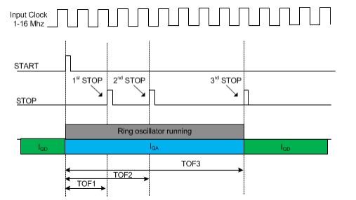
TDC7200 has two measurement modes. Mode 1 can be used to measure ToF between 12ns to 500ns. In mode 1, TDC7200 performs this operation by counting from the START to the last STOP using its internal ring oscillator plus coarse counter. Figure 1-1 explains the measurement of TDC7200 in measurement mode 1.
 Figure 1-1 Measurement Mode 1 in
TDC7200
Figure 1-1 Measurement Mode 1 in
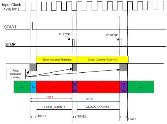
TDC7200In measurement mode 2, the internal ring oscillator of TDC7200 is used to count the fractional parts of the total ToF. The internal ring oscillator starts counting from when it receives the START signal until the first rising edge of the CLOCK. Then, the internal ring oscillator switches off, and the Clock counter starts counting the clock cycles of the external CLOCK input until a STOP pulse is received. The internal ring oscillator again starts counting from the STOP signal until the next rising edge of the CLOCK. This is shown in Figure 1-2.
 Figure 1-2 Measurement Mode 2 in
TDC7200
Figure 1-2 Measurement Mode 2 in
TDC7200Does your application require you to measure distances or fluid level/concentration? If so, you will need TDC7200 to perform the ToF measurements. Let us know by leaving a note in the comments section below.
Additional Resources
- Check out the ultrasonic TDC flowmeter TI Design reference design.
- Learn more about TI’s TDCs.
- Learn more about ultrasonic sensing.
- Read other blog posts about ultrasonic sensing.
- Search for answers, share knowledge and get help in the TI E2E™ Community Ultrasonic Sensing forum.
IMPORTANT NOTICE AND DISCLAIMER
TI PROVIDES TECHNICAL AND RELIABILITY DATA (INCLUDING DATASHEETS), DESIGN RESOURCES (INCLUDING REFERENCE DESIGNS), APPLICATION OR OTHER DESIGN ADVICE, WEB TOOLS, SAFETY INFORMATION, AND OTHER RESOURCES “AS IS” AND WITH ALL FAULTS, AND DISCLAIMS ALL WARRANTIES, EXPRESS AND IMPLIED, INCLUDING WITHOUT LIMITATION ANY IMPLIED WARRANTIES OF MERCHANTABILITY, FITNESS FOR A PARTICULAR PURPOSE OR NON-INFRINGEMENT OF THIRD PARTY INTELLECTUAL PROPERTY RIGHTS.
These resources are intended for skilled developers designing with TI products. You are solely responsible for (1) selecting the appropriate TI products for your application, (2) designing, validating and testing your application, and (3) ensuring your application meets applicable standards, and any other safety, security, or other requirements. These resources are subject to change without notice. TI grants you permission to use these resources only for development of an application that uses the TI products described in the resource. Other reproduction and display of these resources is prohibited. No license is granted to any other TI intellectual property right or to any third party intellectual property right. TI disclaims responsibility for, and you will fully indemnify TI and its representatives against, any claims, damages, costs, losses, and liabilities arising out of your use of these resources.
TI’s products are provided subject to TI’s Terms of Sale (www.ti.com/legal/termsofsale.html) or other applicable terms available either on ti.com or provided in conjunction with such TI products. TI’s provision of these resources does not expand or otherwise alter TI’s applicable warranties or warranty disclaimers for TI products.
Mailing Address: Texas Instruments, Post Office Box 655303, Dallas, Texas 75265
Copyright © 2023, Texas Instruments Incorporated