-
How to Spin Your Stepper Motor More Efficiently, Part 1
How to Spin Your Stepper Motor More Efficiently, Part 1
Matt Hein
It’s no secret that we love stepper motors here at TI. We love them so much that we work to come up with integrated circuits (ICs) and development tools that make stepper motors easier and easier to drive. We have small-form-factor BoosterPacks to encourage prototyping; innovative product features like adaptive decay to eliminate motor tuning; and a wealth of driver ICs with integrated indexers, integrated or external power stages, and the full gamut of protection features.
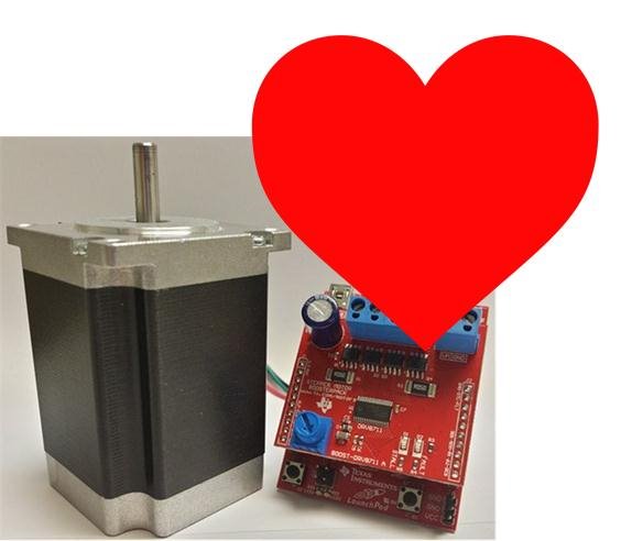
 Figure 1 The DRV8711 BoosterPack: TI’s Adoration for
Stepper Motors Is Unfortunately Not Reciprocated
Figure 1 The DRV8711 BoosterPack: TI’s Adoration for
Stepper Motors Is Unfortunately Not ReciprocatedStepper motors are unique among their motor comrades because they make position control really, really easy. Brushed and brushless DC motors require closed-loop position feedback in order to control where the rotor is; steppers are driven open loop so that you always know what step the rotor is at. This makes the stepper motor useful for a wealth of applications: stage lighting, security cameras, cash machines, medical analyzers, textile equipment, and scanners and printers. 3-D printing is an awesome example of using stepper motors to control position.
 Figure 2 3D Printed Figures: No One
Understands the Benefits of 3-D Printers until They Get to Print These Little
Guys Out
Figure 2 3D Printed Figures: No One
Understands the Benefits of 3-D Printers until They Get to Print These Little
Guys OutThe disadvantage of the stepper motor is the same as its advantage – it is driven open loop. To prevent the motor from stalling, steppers must be driven with enough current so that the motor has adequate torque margin for any situation. This means that stepper motors may run a little bit hot, especially compared to their brushless-DC counterparts. Stepper motors can be very power-hungry.
I spent some time researching how to run a stepper motor more efficiently and asked myself several critical questions:
- If the stepper motor is running unloaded, is there any way to detect that free-spinning condition and decrease the output current?
- If the motor load increases, can you increase the current to prevent the motor from stalling?
- Can I actually write a blog about stepper motors without spending half the time talking about current regulation?
 Figure 3 Current Regulation in a
Stepper Motor During Increasing and Decreasing Steps: No – I Will Not Give
in!
Figure 3 Current Regulation in a
Stepper Motor During Increasing and Decreasing Steps: No – I Will Not Give
in!Leaving the last question aside and hoping for the best, I looked into methods of determining load on a stepper motor. Motor back electromotive force (EMF) seemed promising, as the back-EMF voltage will decrease as the motor is loaded down. At least in theory, you can look at the back EMF and set the stepper-driver output current based on that back-EMF measurement.
My theoretical system magically measures the back EMF and sends the data to the controller. The controller adjusts the stepper-driver output current back into the stepper motor, thereby creating closed-loop operation. The only caveat is that back EMF is only present when the motor is spinning. So this method will not work if the stepper motor is holding position or rotating very slowly.
 Figure 4 Step 1: Spin Motor. Step 2:
Back EMF. Step 3: ?? Step 4: Profit.
Figure 4 Step 1: Spin Motor. Step 2:
Back EMF. Step 3: ?? Step 4: Profit.Back EMF can be difficult to measure in any motor because it gets hidden when the motor windings are energized. As current flows through the winding, the voltage you see across the motor is equal to the back EMF plus the I x R from the resistance of the motor. You would need to back-calculate what the back EMF is, based on what you know about the motor and the current. This calculation method seems pretty difficult, so I don’t want to do it. And I’m very thankful that I don’t have to, because whenever a stepper motor is being microstepped, there is a step in which the current through the winding is zero. This “zero current step” seems to be the perfect time to measure the motor back EMF.
 Figure 5 On Falling Steps, Use a More
Aggressive Current Regulation ... WAIT! NOT SUPPOSED to TALK about THIS
Figure 5 On Falling Steps, Use a More
Aggressive Current Regulation ... WAIT! NOT SUPPOSED to TALK about THISOf course, now we need to know when this zero-current step occurs so that we can actually measure the back EMF at the right time. This is very difficult because most stepper drivers with indexers will not tell you each time they reach a zero-current step. So you will either have to find a stepper driver that automatically samples the back EMF, or go the difficult route and manually drive the stepper motor with two independent H-bridges and control each step of the current waveform with the controller.
Spoiler Alert
: The DRV8711 is a stepper gate driver that actually samples the back EMF for you.
In the next installment of this blog series, I’ll go into detail about my prototype of a power-efficient stepper driver using the DRV8711 BoosterPack and MSP430™ LaunchPad Value Line development kit.