-
Addressing design challenges with user-programmable power-management integrated circuits SSZTCZ8 September 2023 TPS65219 , TPS65219-Q1 , TPS6521905 , TPS6521905-Q1
-
Addressing design challenges with user-programmable power-management integrated circuits
Addressing design challenges with user-programmable power-management integrated circuits
Louise Yang
Advancements in processor and field-programmable gate array (FPGA) technology are complicating power requirements. In addition to supplying the correct voltages and currents to power rails, many power solutions need features such as power sequencing (the activation of power rails in a certain order), low-power modes and monitoring elements.
While it is possible to build a solution using discrete parts, power-management integrated circuits (PMICs) can accelerate the design process. PMICs unify many common power-management functions into a single energy-efficient chip, which can simplify designs and shrink power solution sizes.
Advantages of user-programmable PMICs
There are many types of PMICs: factory-programmed, hardware-configurable and software-configurable. But in situations where wide flexibility and easy customization are high priorities, a user-programmable PMIC can be a better fit, giving impressive control over details such as power rail voltages and power sequencing. Linux® drivers developed specifically for these PMICs enable the system to trigger reboots, soft restarts and low-power modes; they also enable dynamic voltage scaling, adapting buck-converter voltages to match the system’s current power needs.
It is common for a system’s power requirements to change during the design process. You might add or remove peripheral parts, upgrade or swap processors, or want different power modes.
A good example would be the FPGA. The reconfigurability of the FPGA is one of its strongest selling points, but any change to its design and dynamic load requirements will also affect its power-management requirements.
When it comes to customization, the other kinds of PMICs have limitations. For example:
- Factory-programmed PMICs are catalog or custom devices that are pre-programmed to power specific processors or FPGAs, and require a large-volume business case.
- Hardware-configurable PMICs use resistors to change the output voltages, which may lead to power solutions with a larger printed circuit board footprint. Also, adding power sequencing will then require an external sequencer or microcontroller.
- Software-configurable PMICs need an accompanying microcontroller to configure them at startup; these configuration changes are not permanent, and the PMIC must be reconfigured after each power cycle.
Any category of PMIC can offer some level of adjustment to these changing requirements, but the customizability of a user-programmable PMIC is a solid complement to the adaptability of the FPGA; user-programmable PMICs can reduce the amount of time revising FPGA power architectures without compromising the quality of power solutions, giving you more flexibility to experiment with different FPGA designs.
It is possible to reprogram a user-programmable PMIC such as the TPS6521905 multiple times through its electrically erasable programmable read-only memory (EEPROM). The TPS6521905 is initialized with a blank EEPROM, disabling all power rails until configuration and avoiding any potential damage during the production process if you will be powering and placing the PMIC into the prototype board before reprogramming.
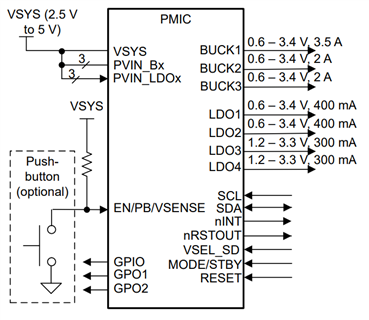
Figure 1 is a block diagram of the TPS6521905.
 Figure 1 Block diagram of the TPS6521905
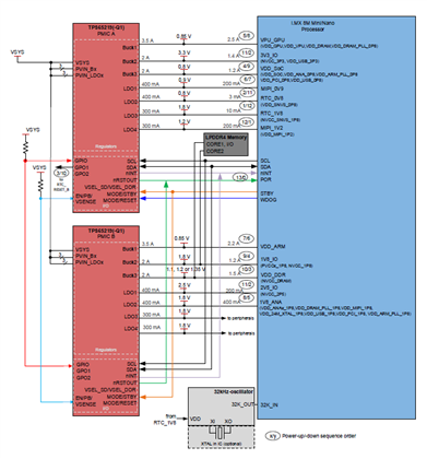
Using I2C communication, you can program the three buck converters and four low-dropout regulators of the TPS6521905 to customize power rail voltages and power sequences and toggle different operating modes. You can set safety features such as undervoltage sensing and temperature thresholds, and configure the three multifunction pins and three digital input/output pins to interface with other devices. If the system needs more power rails, then you can synchronize multiple TPS6521905 devices, as illustrated in Figure 2.
 Figure 2 Cascading multiple TPS6521905 devices
The TPS6521905 comes in a package size as small as 4 mm by 4 mm, and operates at a switching frequency of 2.3 MHz; the compact sizing and high switching frequency allow for smaller input/output inductance and capacitance requirements, which can save space and lower system costs.
Prototyping to production
A user-programmable PMIC is a blank slate with many customization options. It can reduce design cost and time, and is often reusable across different projects. It is possible to reprogram a single part number to substitute several for different part numbers, simplifying the supply chain.
Let’s go through the steps of the prototyping-to-production process with a user-programmable PMIC such as the TPS6521905:
- Define the specifications of the nonvolatile memory settings according to your power solution requirements.
- Reprogram the TPS6521905 with the TPS65219-GUI and TPS65219EVM-SKT, using the programming guide and tutorial video as references.
- Perform testing and validation on the configured PMIC, reevaluating the design until it satisfies your system requirements.
- Once you have finalized the design, export the custom TPS65219-GUI register settings.
- Your company can mass-program the TPS6521905 registers independently or use a third-party programming service.
Conclusion
A user-programmable PMIC can be a good choice given its many customization options; it can also accelerate design processes and reduce system costs while maintaining power efficiency and compact sizing.
Working with user-programmable PMICs can be a new experience for engineers. TI aims to ease the process and offer technical support at every step of the way through user-programmable PMIC user guides, tutorial videos and application notes, as well as the TI E2E™ design support forums.
Additional resources
- Download the TPS6521905 data sheet.
- Learn how to program a PMIC with the “TPS65219 NVM Programming Guide.”