MSP432 and LaunchPad are trademarks of Texas Instruments.
Bluetooth is a registered trademark of Bluetooth SIG, Inc.
All trademarks are the property of their respective owners.
The TI CC256XCQFN-EM board is used to evaluate the dual-mode Bluetooth CC2564C controller, which supports classic Bluetooth and Bluetooth low energy (LE) wireless technology. The CC256XCQFN-EM board works with the following hardware development kits:
Refer to the CC256XEM-STADAPT Quick Start Guide for a list of compatible STM32 MCU Evaluation Boards.
The CC256xC Bluetooth device is a complete basic rate (BR), enhanced data rate (EDR), and LE host controller interface (HCI) solution that reduces design effort and enables fast time to market. Based on TI’s seventh-generation core, the module is a product-proven solution supporting Bluetooth 4.2 dual-mode protocols (5.1 compliant).
Figure 1-1 shows the CC256XCQFN-EM board.
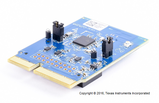
The CC256XCQFN-EM kit contains the following contents:
For a complete evaluation, the CC256XCQFN-EM board requires hardware and software tools selected from the following lists.
Figure 3-1 shows example hardware setups for the CC256XCQFN-EM board using the MSP-EXP432P401R LaunchPad and the BOOST-CCEMADAPTER boards.
Figure 3-2 shows the example hardware setup for the CC256XCQFN-EM board using the CC256XEM-STADAPT and the STM3240G-EVAL board.
The CC256XCQFN-EM board supports the following connectors:
Figure 4-1 shows the connectors on the front side of the CC256XCQFN-EM board.
Figure 4-2 shows the connectors on the back side of the CC256XCQFN-EM board.
This section describes the settings for the EM connector and the COM connector.
The CC256XCQFN-EM can be mounted on TI MCU platforms such as the MSP-EXP432P401R using the BOOST-CCEMADAPTER. The CC256XCQFN-EM EM1/EM2 connectors can also be used with the CC256XEM-STADAPT to mount the CC256XCQFN-EM on other MCU platforms.
All EM I/Os are at 3.3-V levels. Pin assignments are described with respect to the front (CC2564C) side. For example, MODULE_UART_RX refers to the receiving UART RX pin on the CC256xC device that connects to the UART_TX pin on the MCU.
Table 5-1 describes the standard pinout for EM1.
Pin | EM Adapter Assignment(1) | Pin | EM Adapter Assignment(1) |
---|---|---|---|
1 | GND | 2 | NC |
3 | MODULE_UART_CTS | 4 | NC |
5 | SLOW_CLK | 6 | NC |
7 | MODULE_UART_RX | 8 | NC |
9 | MODULE_UART_TX | 10 | NC |
11 | NC | 12 | NC |
13 | NC | 14 | NC |
15 | NC | 16 | NC |
17 | NC | 18 | NC |
19 | GND | 20 | NC |
Table 5-2 describes the standard pinout for EM2.
Pin | EM Adapter Assignment(1) | Pin | EM Adapter Assignment(1) |
---|---|---|---|
1 | NC | 2 | GND |
3 | NC | 4 | NC |
5 | NC | 6 | NC |
7 | 3.3 V | 8 | MODULE_AUDIO_DATA_OUT |
9 | 3.3 V | 10 | MODULE_AUDIO_DATA_IN |
11 | MODULE_AUDIO_FSINK | 12 | NC |
13 | NC | 14 | NC |
15 | NC | 16 | NC |
17 | MODULE_AUDIO_CLK | 18 | MODULE_UART_RTS |
19 | nSHUTD | 20 | NC |
For complete evaluation of the audio applications with the MSP432 LaunchPad and STM32 Evaluation boards, the level shifter U4 must be properly configured to ensure proper direction of PCM signals.
More information on the hardware changes required for PCM signals on EM connectors is in the Dual-Mode Bluetooth CC2564C Evaluation Board User's Guide and the CC256XCQFN-EM board design files (schematics and bill of materials).
The COM connector interfaces with TI's MPU platforms, such as the AM335x evaluation module (TMDXEVM3358).
Table 5-3 describes the COM connector pinout.
Pin(1) | Relevant COM Connector Pin Assignment |
---|---|
1 | SLOW_CLK_EDGE |
8 | 1V8_IN |
52 | AUD_CLK_1V8 |
54 | AUD_FSYNC_1V8 |
56 | AUD_IN_1V8 |
58 | AUD_OUT_1V8 |
66 | HCI_TX_1V8 |
68 | HCI_RX_1V8 |
70 | HCI_CTS_1V8 |
72 | HCI_RTS_1V8 |
76 | TX_DEBUG_1V8 |
89 | nSHUTDOWN_1V8 |
3, 9, 19, 37, 47, 63, 77, 83, 87, 95, 97 | GND |
2, 6, 18, 22, 42, 60, 64, 92 | GND |
TI PROVIDES TECHNICAL AND RELIABILITY DATA (INCLUDING DATASHEETS), DESIGN RESOURCES (INCLUDING REFERENCE DESIGNS), APPLICATION OR OTHER DESIGN ADVICE, WEB TOOLS, SAFETY INFORMATION, AND OTHER RESOURCES “AS IS” AND WITH ALL FAULTS, AND DISCLAIMS ALL WARRANTIES, EXPRESS AND IMPLIED, INCLUDING WITHOUT LIMITATION ANY IMPLIED WARRANTIES OF MERCHANTABILITY, FITNESS FOR A PARTICULAR PURPOSE OR NON-INFRINGEMENT OF THIRD PARTY INTELLECTUAL PROPERTY RIGHTS. |
These resources are intended for skilled developers designing with TI products. You are solely responsible for (1) selecting the appropriate TI products for your application, (2) designing, validating and testing your application, and (3) ensuring your application meets applicable standards, and any other safety, security, or other requirements. These resources are subject to change without notice. TI grants you permission to use these resources only for development of an application that uses the TI products described in the resource. Other reproduction and display of these resources is prohibited. No license is granted to any other TI intellectual property right or to any third party intellectual property right. TI disclaims responsibility for, and you will fully indemnify TI and its representatives against, any claims, damages, costs, losses, and liabilities arising out of your use of these resources. |
TI’s products are provided subject to TI’s Terms of Sale (www.ti.com/legal/termsofsale.html) or other applicable terms available either on ti.com or provided in conjunction with such TI products. TI’s provision of these resources does not expand or otherwise alter TI’s applicable warranties or warranty disclaimers for TI products. |
Mailing Address: Texas Instruments, Post Office Box 655303, Dallas, Texas 75265
Copyright © 2021, Texas Instruments Incorporated |