-
Pre-Regulated Isolated Driver Bias Supply Reference Design for Traction-Inverter Applications
TECHNICAL REFERENCE
Pre-Regulated Isolated Driver Bias Supply Reference Design for Traction-Inverter Applications
1 Description
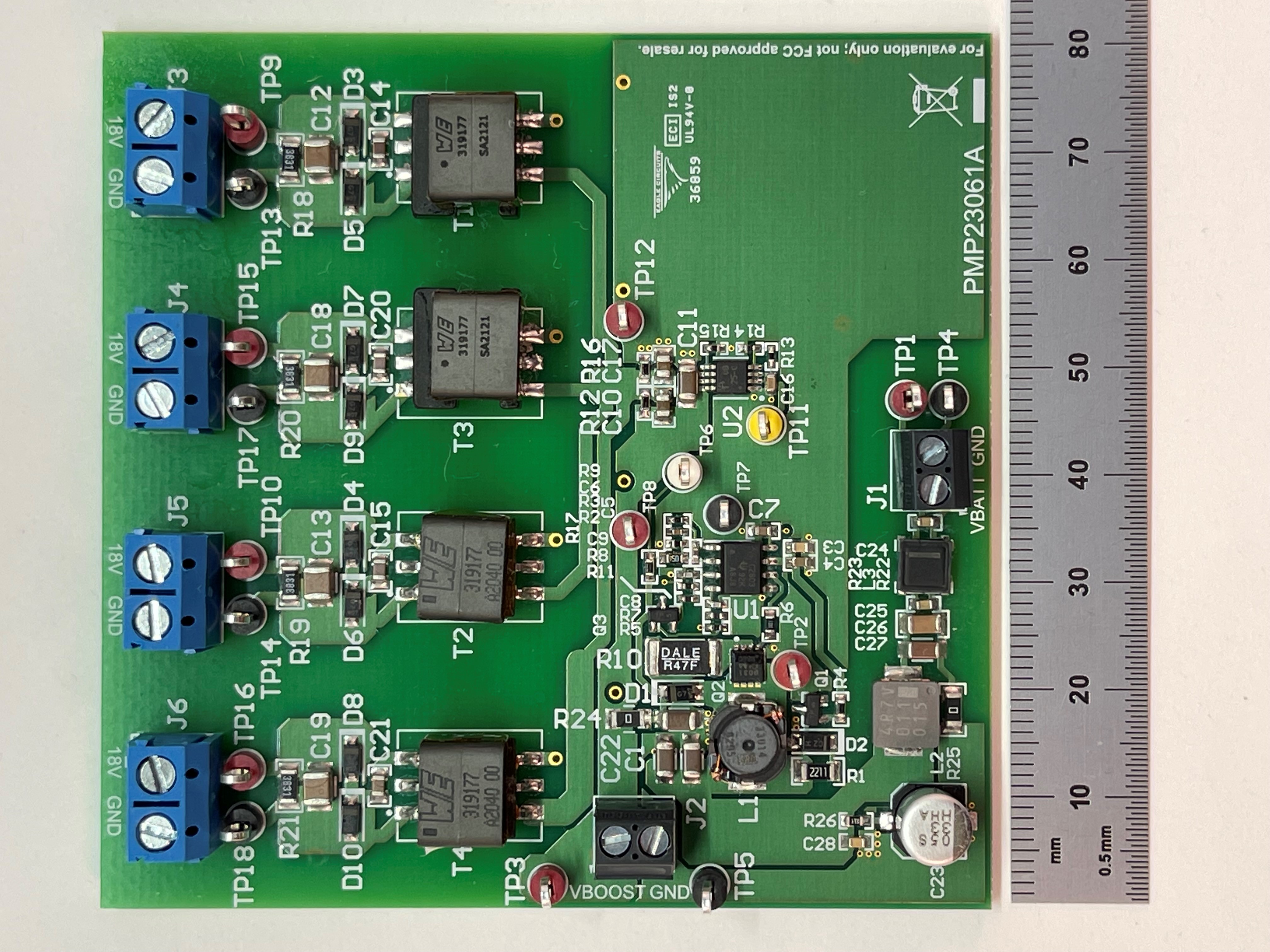
This pre-regulated isolated open-loop LLC transformer driver converter provides four 18-V outputs up to a total of 6 W for traction-inverter applications. The LLC topology allows the transformer to have significant leakage inductance, but a much smaller primary-secondary capacitance, which significantly reduces common-mode current injection through the bias transformer. The boost pre-regulator is designed to provide 7.5 W to the LLC converter, which can support a maximum of 6-W output.
 Figure 1-1 Top Photo
2 Test Prerequisites
2.1 Voltage and Current Requirements
Table 2-1 Voltage and Current
Requirements
| Parameter | Specifications |
|---|---|
| Input voltage range | 6 V–28 V |
| Output voltage and current | 4 × 18-V rails, 1 × 167 mA, 3 × 56 mA, 6 W maximum |
| Switching frequency | Boost: 300 kHz, LLC: 1 MHz |
| Isolation | Yes |
| Topology | Open-loop LLC transformer driver with boost pre-regulator |
2.2 Required Equipment
- Resistive loads
- Power supply capable of 30 V, 10 W minimum
- Oscilloscope and probes
- Digital multimeters