-
LM3269 Seamless-Transition Buck-Boost Converter for 3G and 4G RF Power Amplifiers
- 1 Features
- 2 Applications
- 3 Description
- 4 Revision History
- 5 Pin Configuration and Functions
- 6 Specifications
- 7 Detailed Description
- 8 Application and Implementation
- 9 Power Supply Recommendations
- 10Layout
- 11Device and Documentation Support
- 12Mechanical, Packaging, and Orderable Information
- IMPORTANT NOTICE
Package Options
Mechanical Data (Package|Pins)
- YZR|12
Thermal pad, mechanical data (Package|Pins)
Orderable Information
LM3269 Seamless-Transition Buck-Boost Converter for 3G and 4G RF Power Amplifiers
1 Features
- Operates From a Single Li-Ion Cell: 2.7 V to 5.5 V
- Adjustable Output Voltage: 0.6 V to 4.2 V
- Automatic PFM or PWM Mode Change
- 750-mA Maximum Load Capability for
VBATT ≥ 3 V, VOUT = 3.8 V - 2.4-MHz (typical) Switching Frequency
- Seamless Buck-Boost Mode Transition
- Fast Output Voltage Transition: 1.4 V to 3 V
in 10 µs - High-Efficiency: 95% typical at VBATT = 3.7 V, VOUT = 3.3 V, at 300 mA
- Input Overcurrent Limit
- Internal Compensation
2 Applications
- Power Supply for 3G/4G Power Amplifiers
- Cellular Phones
- Portable Hard Disk Drives
- PDAs
3 Description
The LM3269 is buck-boost DC-DC converter designed to generate output voltages above or below a given input voltage and is particularly suitable for portable applications powered by a single-cell Li-ion battery.
The LM3269 operates at a 2.4-MHz typical switching frequency in full synchronous operation and provides seamless transitions between buck and boost operating regimes. The LM3269 operates in energy-saving Pulse Frequency Modulation (PFM) mode for increased efficiencies and current savings during low-power RF transmission modes.
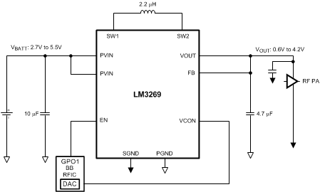
The power converter topology needs only one inductor and two capacitors. A unique internal power switch topology enables high overall efficiency.
The LM3269 is internally compensated for buck and boost modes of operation, thus providing an optimal transient response.
When considering using the LM3269 in a system design, please review the layout instruactions at the end of this document.
Device Information(1)
| PART NUMBER | PACKAGE | BODY SIZE (MAX) |
|---|---|---|
| LM3269 | DSBGA (12) | 2.529 mm x 2.022 mm |
- For all available packages, see the orderable addendum at the end of the data sheet.
Typical Application

4 Revision History
Changes from C Revision (May 2013) to D Revision
- Added Device Information table, Pin Configuration and Functions section, ESD Rating table, Feature Description , Device Functional Modes, Application and Implementation, Power Supply Recommendations, Device and Documentation Support , and Mechanical, Packaging, and Orderable Information sectionsGo
- Deleted Recommended Capacitance Specifications table as info contained in other tablesGo
Changes from B Revision (August 2012) to C Revision
- Changed product brief to full data sheet Go
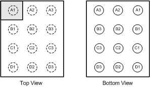
5 Pin Configuration and Functions

Pin Functions
| PIN | TYPE(1) | DESCRIPTION | |
|---|---|---|---|
| NUMBER | NAME | ||
| A1 | NC | — | Non Connection. Leave this pin floating; do not connect to PVIN or PGND. |
| A2 | NC | — | Non Connection. Leave this pin floating, do not connect to PVIN or PGND. |
| A3 | PVIN | P/I | Power MOSFET input and power current input pin. Optional low-pass filtering may help buck and buck-boost modes for radiated EMI and noise reduction. |
| B1 | VCON | A/I | Voltage Control analog input. VCON controls the output voltage in PWM and PFM modes. |
| B2 | EN | D/I | Enable pin. Pulling this pin higher than 1.2 V enables part to function. |
| B3 | PVIN | P/I | Power MOSFET input and power current input pin. Optional low-pass filtering may help buck and buck-boost modes for radiated EMI and noise reduction. |
| C1 | FB | A | Feedback input to inverting input of error amplifier. Connect output voltage directly to this node at load point. |
| C2 | SGND | G | Signal Ground for analog circuits and control circuitry. |
| C3 | SW1 | P/O | Switch pin for Internal Power Switches. Connect inductor between SW1 and SW2. |
| D1 | VOUT | O | Regulated output voltage of the LM3269. Connect this to a 4.7-µF ceramic output filter capacitor to GND. |
| D2 | SW2 | P/O | Switch pin for Internal Power Switches. Connect inductor between SW1 and SW2. |
| D3 | PGND | G | Power Ground for Power MOSFETs and gate drive circuitry. |