SNVS450F September   2006  – October 2015 LM3402 , LM3402HV

PRODUCTION DATA.  

  1. Features
  2. Applications
  3. Description
  4. Revision History
  5. Pin Configuration and Functions
  6. Specifications
    1. 6.1 Absolute Maximum Ratings
    2. 6.2 ESD Ratings
    3. 6.3 Recommended Operating Conditions
    4. 6.4 Thermal Information
    5. 6.5 Electrical Characteristics
    6. 6.6 Timing Requirements
    7. 6.7 Typical Characteristics
  7. Detailed Description
    1. 7.1 Overview
    2. 7.2 Functional Block Diagram
    3. 7.3 Feature Description
      1. 7.3.1 Controlled ON-time Overview
      2. 7.3.2 Average LED Current Accuracy
      3. 7.3.3 Maximum Output Voltage
      4. 7.3.4 Minimum Output Voltage
      5. 7.3.5 High Voltage Bias Regulator
      6. 7.3.6 Internal MOSFET and Driver
      7. 7.3.7 Fast Shutdown for PWM Dimming
      8. 7.3.8 Peak Current Limit
      9. 7.3.9 Overvoltage and Overcurrent Comparator
    4. 7.4 Device Functional Modes
      1. 7.4.1 Low Power Shutdown
      2. 7.4.2 Thermal Shutdown
  8. Application and Implementation
    1. 8.1 Application Information
      1. 8.1.1 Switching Frequency
      2. 8.1.2 LED Ripple Current
      3. 8.1.3 Buck Converters Without Output Capacitors
      4. 8.1.4 Buck Converters With Output Capacitors
      5. 8.1.5 Input Capacitors
      6. 8.1.6 Recirculating Diode
      7. 8.1.7 LED Current During DIM Mode
      8. 8.1.8 Transient Protection Considerations
        1. 8.1.8.1 CS Pin Protection
        2. 8.1.8.2 CS Pin Protection With OVP
        3. 8.1.8.3 VIN Pin Protection
        4. 8.1.8.4 General Comments Regarding Other Pins
    2. 8.2 Typical Application
      1. 8.2.1 Design Requirements
      2. 8.2.2 Detailed Design Procedure
        1. 8.2.2.1 RON and tON
        2. 8.2.2.2 Using an Output Capacitor
        3. 8.2.2.3 Output Inductor
          1. 8.2.2.3.1 RSNS
        4. 8.2.2.4 Input Capacitor
        5. 8.2.2.5 Recirculating Diode
          1. 8.2.2.5.1 CB and CF
        6. 8.2.2.6 Efficiency
        7. 8.2.2.7 Die Temperature
      3. 8.2.3 Application Curves
  9. Power Supply Recommendations
  10. 10Layout
    1. 10.1 Layout Guidelines
      1. 10.1.1 Compact Layout
      2. 10.1.2 Ground Plane and Shape Routing
      3. 10.1.3 Current Sensing
      4. 10.1.4 Remote LED Arrays
    2. 10.2 Layout Example
  11. 11Device and Documentation Support
    1. 11.1 Device Support
      1. 11.1.1 Third-Party Products Disclaimer
    2. 11.2 Related Links
    3. 11.3 Community Resources
    4. 11.4 Trademarks
    5. 11.5 Electrostatic Discharge Caution
    6. 11.6 Glossary
  12. 12Mechanical, Packaging, and Orderable Information

Package Options

Mechanical Data (Package|Pins)
Thermal pad, mechanical data (Package|Pins)
Orderable Information

1 Features

  • Integrated 0.5-A N-channel MOSFET
  • VIN Range from 6 V to 42 V (LM3402)
  • VIN Range from 6 V to 75 V (LM3402HV)
  • 500 mA Output Current Over Temperature
  • Cycle-by-Cycle Current Limit
  • No Control Loop Compensation Required
  • Separate PWM Dimming and Low Power Shutdown
  • Supports All Ceramic-Output Capacitors and Capacitor-Less Outputs
  • Thermal Shutdown Protection
  • VSSOP, SO PowerPAD™ Packages

2 Applications

  • LED Drivers
  • Constant Current Source
  • Automotive Lighting
  • General Illumination
  • Industrial Lighting

3 Description

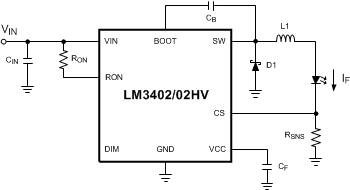
The LM3402/HV are monolithic switching regulators designed to deliver constant currents to high power LEDs. Ideal for automotive, industrial, and general lighting applications, they contain a high-side N-channel MOSFET switch with a current limit of 735 mA (typical) for step-down (Buck) regulators. Hysteretic control with controlled ON-time coupled with an external resistor allow the converter output voltage to adjust as needed to deliver a constant current to series and series - parallel connected arrays of LEDs of varying number and type, LED dimming by pulse width modulation (PWM), broken/open LED protection, low-power shutdown and thermal shutdown complete the feature set.

Device Information(1)

PART NUMBER PACKAGE BODY SIZE (NOM)
LM3402/HV VSSOP (8) 3.00 mm × 3.00 mm
HSOP (8) 4.89 mm × 3.90 mm
  1. For all available packages, see the orderable addendum at the end of the data sheet.

Typical Application Diagram
LM3402 LM3402HV 20192101.gif