-
LM5161 Wide Input 100-V, 1-A Synchronous Buck/Fly-Buck™ Converter
- 1 Features
- 2 Applications
- 3 Description
- 4 Revision History
- 5 Pin Configuration and Functions
- 6 Specifications
-
7 Detailed Description
- 7.1 Overview
- 7.2 Functional Block Diagram
- 7.3
Feature Description
- 7.3.1 Control Circuit
- 7.3.2 VCC Regulator
- 7.3.3 Regulation Comparator
- 7.3.4 Soft-Start
- 7.3.5 Error Transconductance (GM) Amplifier
- 7.3.6 On-Time Generator
- 7.3.7 Current Limit
- 7.3.8 N-Channel Buck Switch and Driver
- 7.3.9 Synchronous Rectifier
- 7.3.10 Enable / Undervoltage Lockout (EN/UVLO)
- 7.3.11 Thermal Protection
- 7.4 Device Functional Modes
-
8 Applications and Implementation
- 8.1 Application Information
- 8.2
Typical Applications
- 8.2.1
LM5161 Synchronous Buck (15-V to 95-V Input, 12-V Output, 1-A Load)
- 8.2.1.1 Design Requirements
- 8.2.1.2
Detailed Design Procedure
- 8.2.1.2.1 Custom Design With WEBENCH® Tools
- 8.2.1.2.2 Output Resistor Divider Selection
- 8.2.1.2.3 Frequency Selection
- 8.2.1.2.4 Inductor Selection
- 8.2.1.2.5 Output Capacitor Selection
- 8.2.1.2.6 Series Ripple Resistor - RESR (FPWM = 1)
- 8.2.1.2.7 VCC and Bootstrap Capacitor
- 8.2.1.2.8 Input Capacitor Selection
- 8.2.1.2.9 Soft-Start Capacitor Selection
- 8.2.1.2.10 EN/UVLO Resistor Selection
- 8.2.1.3 Application Curves
- 8.2.2 LM5161 Isolated Fly-Buck (36-V to 72-V Input, 12-V, 12-W Isolated Output)
- 8.2.3 Ripple Configuration
- 8.2.1
LM5161 Synchronous Buck (15-V to 95-V Input, 12-V Output, 1-A Load)
- 8.3 Do's and Don'ts
- 9 Power Supply Recommendations
- 10Layout
- 11Device and Documentation Support
- 12Mechanical, Packaging, and Orderable Information
- IMPORTANT NOTICE
Package Options
Mechanical Data (Package|Pins)
- PWP|14
Thermal pad, mechanical data (Package|Pins)
- PWP|14
Orderable Information
LM5161 Wide Input 100-V, 1-A Synchronous Buck/Fly-Buck™ Converter
1 Features
- Wide 4.5-V to 100-V Input Voltage Range
- Integrated High-Side and Low-Side Switches
- No Schottky Diode Required
- 1-A Maximum Load Current
- Constant ON-Time Control
- No External Loop Compensation
- Fast Transient Response
- Selectable DCM Buck Operation at Light Load
- CCM Option Supports Multi-Output Fly-Buck™
- No External Ripple circuit needed (at FPWM = 0)
- Nearly Constant Switching Frequency
- Frequency Adjustable Up to 1 MHz
- Programmable Soft-Start Time
- Prebias Start-Up
- Peak Current Limiting Protection
- Adjustable Input UVLO and Hysteresis
- ±1% Feedback Voltage Reference
- Thermal Shutdown Protection
- Create a Custom Design Using the LM5161 With the WEBENCH® Power Designer
2 Applications
- Industrial Programmable Logic Controller
- IGBT Gate Drive Bias Supply
- Telecom DC-DC Primary and Secondary Side Bias
- E-Meter Power Line Communication
- Low-Power (<12W), Isolated DC-DC (Fly-Buck)
3 Description
The LM5161 is a 100-V, 1-A synchronous step-down converter with integrated high-side and low-side MOSFETs. The constant-ON-time control scheme requires no loop compensation and supports high step-down ratios with fast transient response. An internal feedback amplifier maintains ±1% output voltage regulation over the entire operating temperature range. The ON-time varies inversely with input voltage resulting in nearly constant switching frequency. Peak and valley current limit circuits protect against overload conditions. The under-voltage lockout (EN/UVLO) circuit provides independently adjustable input undervoltage threshold and hysteresis. The FPWM input pin in LM5161 selects either the forced continuous conduction mode (CCM) under all load levels or the discontinuous conduction mode (DCM) under light or no load conditions. When operating in forced CCM, the LM5161 supports the multiple output and isolated Fly-Buck applications. When programmed for the DCM operation, the LM5161 provides a tightly regulated buck output without any additional external feedback ripple injection circuit.
Device Information(1)
| PART NUMBER | PACKAGE | BODY SIZE (NOM) |
|---|---|---|
| LM5161 | HTSSOP (14) | 5.00 mm × 4.40 mm |
- For all available packages, see the orderable addendum at the end of the data sheet.
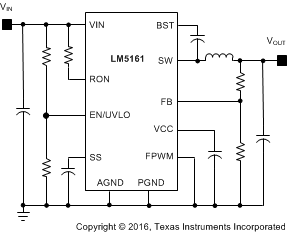
Typical Buck Application Circuit

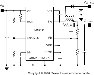
Typical Fly-Buck Application Circuit

5 Pin Configuration and Functions

Pin Functions
| PIN | I/O | DESCRIPTION | |
|---|---|---|---|
| NAME | HTSSOP | ||
| AGND | 1 | - | Analog ground. Ground connection of internal control circuits. |
| PGND | 2 | - | Power ground. Ground connection of the internal synchronous rectifier FET. |
| VIN | 3 | I | Input supply connection. Operating input range is 4.5-V to 100-V. |
| EN/UVLO | 4 | I | Precision enable. Input pin of undervoltage lockout (UVLO) comparator. |
| RON | 5 | I | On-time programming pin. A resistor between this pin and VIN sets the switch ON-time as a function of input voltage. |
| SS | 6 | I | Soft start. Connect a capacitor from SS to AGND to control output rise time and limit overshoot. |
| FPWM | 8 | I | Forced PWM logic input pin. Connect to AGND for discontinuous conduction mode (DCM) with light loads. Connect to VCC for continuous conduction mode (CCM) at all loads and Fly-Buck configuration. |
| FB | 9 | I | Feedback input of voltage regulation comparator. |
| VCC | 10 | O | Internal high voltage start-up regulator bypass capacitor pin. |
| BST | 11 | I | Bootstrap capacitor pin. Connect a capacitor between BST and SW to bias gate driver of high-side buck FET. |
| SW | 12,13 | O | Switch node. Source connection of high side buck FET and drain connection of low-side synchronous rectifier FET. |
| NC | 7,14 | No connection | |
| EP | - | Exposed pad. Connect to AGND and printed-circuit board ground plane to improve power dissipation. | |
6 Specifications
6.1 Absolute Maximum Ratings
| MIN | MAX | UNIT | ||
|---|---|---|---|---|
| Input voltage | VIN to AGND | –0.3 | 100 | V |
| EN/UVLO to AGND | –0.3 | 100 | ||
| RON to AGND | –0.3 | 100 | ||
| BST to AGND | –0.3 | 114 | ||
| VCC to AGND | –0.3 | 14 | ||
| FPWM to AGND | –0.3 | 14 | ||
| SS to AGND | –0.3 | 7 | ||
| FB to AGND | –0.3 | 7 | ||
| Output voltage | BST to SW | –0.3 | 14 | V |
| BST to VCC | 100 | |||
| SW to AGND | –1.5 | 100 | ||
| SW to AGND (20-ns transient) | –3 | |||
| Maximum junction temperature(3) | –40 | 150 | °C | |
| Storage temperature Tstg | –65 | 150 | °C | |
- Stresses beyond those listed under Absolute Maximum Ratings may cause permanent damage to the device. These are stress ratings only, which do not imply functional operation of the device at these or any other conditions beyond those indicated under Recommended Operating Conditions . Exposure to absolute-maximum-rated conditions for extended periods may affect device reliability.
- If Military/Aerospace specified devices are required, contact the Texas Instruments Sales Office/ Distributors for availability and specifications.
- High junction temperatures degrade operating lifetimes. Operating lifetime is de-rated for junction temperatures greater than 125°C.
6.2 ESD Ratings
| VALUE | UNIT | |||
|---|---|---|---|---|
| V(ESD) | Electrostatic discharge | Human-body model (HBM), per ANSI/ESDA/JEDEC JS-001(1) | ±2000 | V |
| Charged-device model (CDM), per JEDEC specification JESD22-C101(2) | ±750 | |||
6.3 Recommended Operating Conditions
Over operating free-air temperature range (unless otherwise noted)(1)| MIN | NOM | MAX | UNIT | ||
|---|---|---|---|---|---|
| VIN input voltage | 4.5 | 100 | V | ||
| IO output current | 1 | A | |||
| External VCC bias voltage | 9 | 13 | V | ||
| Operating junction temperature(2) | –40 | 125 | °C | ||
6.4 Thermal Information
See (1)| THERMAL METRIC | LM5161 | UNIT | |
|---|---|---|---|
| PWP (HTSSOP) | |||
| 14 PINS | |||
| RθJA | Junction-to-ambient thermal resistance(1) | 39.3 | °C/W |
| RθJCbot | Junction-to-case (bottom) thermal resistance(1) | 2.0 | °C/W |
| ψJB | Junction-to-board thermal characteristic parameter | 19.3 | °C/W |
| RθJB | Junction-to-board thermal resistance | 19.6 | °C/W |
| RθJCtop | Junction-to-case (top) thermal resistance | 22.8 | °C/W |
| ψJT | Junction-to-top thermal characteristic parameter | 0.5 | °C/W |
6.5 Electrical Characteristics
Typical values correspond to TJ = 25°C. Minimum and maximum limits apply over TJ = –40°C to 125°C(1)(2) for LM5161. Unless otherwise stated, VIN = 48 V.| PARAMETER | TEST CONDITIONS | MIN | TYP | MAX | UNIT | |
|---|---|---|---|---|---|---|
| SUPPLY CURRENT | ||||||
| ISD | Input shutdown current | VIN = 48 V, EN/UVLO = 0 V | 50 | 90 | µA | |
| IOP | Input operating current | VIN = 48 V, FB = 3 V, Non-switching | 2.3 | 2.8 | mA | |
| VCC SUPPLY | ||||||
| VCC | Bias regulator output | VIN = 48 V, ICC = 20 mA | 6.3 | 7.3 | 8.5 | V |
| VCC | Bias regulator current limit | VIN = 48 V | 30 | mA | ||
| VCC(UV) | VCC undervoltage threshold | VCC rising | 3.98 | 4.1 | V | |
| VCC(HYS) | VCC undervoltage hysteresis | VCC falling | 185 | mV | ||
| VCC(LDO) | VIN - VCC dropout voltage | VIN = 4.5 V, ICC = 20 mA | 200 | 340 | mV | |
| HIGH-SIDE FET | ||||||
| RDS(ON) | High-side on resistance | V(BST - SW) = 7 V, ISW = 0.5A | 0.58 | Ω | ||
| BST(UV) | Bootstrap gate drive UV | V(BST - SW) rising | 2.93 | 3.6 | V | |
| BST(HYS) | Gate drive UV hysteresis | V(BST - SW) falling | 200 | mV | ||
| LOW-SIDE FET | ||||||
| RDS(ON) | Low-side on resistance | ISW = 0.5 A | 0.24 | Ω | ||
| HIGH-SIDE CURRENT LIMIT | ||||||
| ILIM (HS) | High-side current limit threshold | 1.3 | 1.61 | 1.9 | A | |
| TRES | Current limit response time | ILIM (HS)threshold detect to FET turn-off | 100 | ns | ||
| TOFF | Current limit forced off-time | FB = 0 V, VIN = 72 V | 13 | 16.5 | 21 | µs |
| TOFF1 | Current limit forced off-time | FB = 0.1 V, VIN = 72 V | 10 | 13 | 17 | µs |
| TOFF2 | Current limit forced off-time | FB = 1 V, VIN = 72 V | 2 | 2.7 | 4.1 | µs |
| LOW-SIDE CURRENT LIMIT | ||||||
| ISOURCE(LS) | Sourcing current limit | 1.3 | 1.6 | 1.9 | A | |
| ISINK(LS) | Sinking current limit | 3 | ||||
| DIODE EMULATION | ||||||
| VFPWM(LOW) | FPWM input logic low | VIN = 48 V | 1 | V | ||
| VFPWM(HIGH) | FPWM input logic high | VIN = 48 V | 3 | |||
| IZX | Zero cross detect current | FPWM = 0 (Diode emulation) | 22.5 | mA | ||
| REGULATION COMPARATOR | ||||||
| VREF | FB regulation level | VIN = 48 V | 1.975 | 2 | 2.015 | V |
| I(BIAS) | FB input bias current | VIN = 48 V | 100 | nA | ||
| ERROR CORRECTION AMPLIFIER AND SOFT START | ||||||
| GM | Error amp transconductance | FB = VREF (±) 10 mV | 100 | µA/V | ||
| IEA(SOURCE) | Error amp source current | FB = 1 V, SS = 1 V | 7.5 | 10 | 12.5 | µA |
| IEA(SINK) | Error amp sink current | FB = 5 V, SS = 2.25 V | 7.5 | 10 | 12.5 | |
| V(SS-FB) | VSS - VFB clamp voltage | FB = 1.75 V, CSS= 1 nF | 135 | mV | ||
| ISS | Soft-start charging current | SS = 0.5 V | 7.5 | 10 | 12.5 | µA |
| ENABLE/UVLO | ||||||
| VUVLO (TH) | UVLO threshold | EN/UVLO rising | 1.195 | 1.24 | 1.272 | V |
| IUVLO(HYS) | UVLO hysteresis current | EN/UVLO = 1.4 V | 15 | 20 | 25 | µA |
| VSD(TH) | Shutdown mode threshold | EN/UVLO falling | 0.29 | 0.35 | V | |
| VSD(HYS) | Shutdown threshold hysteresis | EN/UVLO rising | 50 | mV | ||
| THERMAL SHUTDOWN | ||||||
| TSD | Thermal shutdown threshold | 175 | °C | |||
| TSD(HYS) | Thermal shutdown hysteresis | 20 | °C | |||
- All minimum and maximum limits are specified by correlating the electrical characteristics to process and temperature variations and applying statistical process control.
- The junction temperature (TJ in °C) is calculated from the ambient temperature (TA in °C) and power dissipation (PD in Watts) as follows: TJ = TA + (PD • RθJA) where RθJA (in °C/W) is the package thermal impedance provided in the Thermal Information section.
6.6 Switching Characteristics(1)
Typical values correspond to TJ = 25°C. Minimum and maximum limits apply over TJ = –40°C to 125°C for LM5161. Unless otherwise stated, VIN = 48 V.| PARAMETER | TEST CONDITIONS | MIN | TYP | MAX | UNIT | |
|---|---|---|---|---|---|---|
| MINIMUM OFF-TIME | ||||||
| TOFF-MIN | Minimum off-time, FB = 0 V | 170 | ns | |||
| TOFF-MIN | Minimum off-time, FB = 0 V, VIN = 4.5 V | 200 | ns | |||
| ON-TIME GENERATOR | ||||||
| TON Test 1 | VIN = 24 V, RON = 100 kΩ | 420 | 540 | 665 | ns | |
| TON Test 2 | VIN = 48 V, RON = 100 kΩ | 270 | ns | |||
| TON Test 3 | VIN = 8 V, RON = 100 kΩ | 1150 | 1325 | 1500 | ns | |
| TON Test 4 | VIN = 72V, RON = 150 kΩ | 285 | ns | |||
6.7 Typical Characteristics
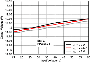
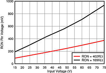
At TA = 25°C and applicable to LM5161 unless otherwise noted.
| VOUT = 3.3 V | RON = 110 kΩ | |
| FPWM = 0 |

| VOUT = 12 V | RON = 402 kΩ | |
| FPWM = 0 | L = 100 µH |

| VOUT = 12 V | RON = 300 kΩ | |
| FPWM = 1 | L = 100 µH |

| VIN = 48 V | ||


| VIN = 48 V | ||

| VIN = 48 V | ||

| VIN = 48 V | ||

| VIN = 48 V | ||

| VOUT = 5 V | RON = 169 kΩ | |
| L=47 µH |

| VOUT = 12 V | RON = 402 kΩ | |
| FPWM = 1 | L = 100 µH |


| IOUT = 1 A | FPWM = 0 | |


| VOUT = 12 V | ||

| VFB = 3 V | ||

| VIN = 48 V | ||

| VIN = 48 V | ||

| VIN = 48 V | ||

| VIN = 48 V | ||

| ISW = 500 mA | VIN = 48 V | |