-
OPA55x High-Voltage, High-Current Operational Amplifiers
- 1 Features
- 2 Applications
- 3 Description
- 4 Revision History
- 5 Pin Configuration and Functions
- 6 Specifications
- 7 Detailed Description
- 8 Application and Implementation
- 9 Power Supply Recommendations
- 10Layout
- 11Device and Documentation Support
- 12Mechanical, Packaging, and Orderable Information
- IMPORTANT NOTICE
Package Options
Mechanical Data (Package|Pins)
Thermal pad, mechanical data (Package|Pins)
Orderable Information
OPA55x High-Voltage, High-Current Operational Amplifiers
1 Features
- Wide Supply Range: ±4 V to ±30 V
- High Output Current: 200 mA Continuous
- Low Noise: 14 nV/√Hz
- Fully Protected:
- Thermal Shutdown
- Output Current-Limited
- Thermal Shutdown Indicator
- Wide Output Swing: 2 V from Rail
- Fast Slew Rate:
- OPA551: 15 V/µs
- OPA552: 24 V/µs
- Wide Bandwidth:
- OPA551: 3 MHz
- OPA552: 12 MHz
- Packages: PDIP-8, SOIC-8, or DDPAK/TO-263-7
2 Applications
- Telephony
- Test Equipment
- Audio Amplifiers
- Transducer Excitation
- Servo Drivers
3 Description
The OPA551x devices are low-cost operational amplifiers with high-voltage (60-V) and high-current (200-mA) capability.
The OPA551 is unity-gain stable and features high slew rate (15 V/µs) and wide bandwidth (3 MHz). The OPA552 is optimized for gains of 5 or greater, and offers higher speed with a slew rate of 24 V/µs and a bandwidth of 12 MHz. Both devices are suitable for telephony, audio, servo, and test applications.
These laser-trimmed, monolithic integrated circuits provide excellent low-level accuracy along with high output swing. High performance is maintained as the amplifier swings to its specified limits.
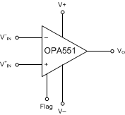
The OPA55x devices are internally protected against overtemperature conditions and current overloads. The thermal shutdown indicator flag provides a current output to alert the user when thermal shutdown has occurred.
The OPA55x devices are available in PDIP-8 and SOIC-8 packages, as well as a DDPAK-7/TO-263 surface-mount plastic power package. They are specified for operation over the extended industrial temperature range, –40°C to +125°C.
Device Information(1)
| PART NUMBER | PACKAGE | BODY SIZE (NOM) |
|---|---|---|
| OPA55x | PDIP (8) | 9.81 mm × 6.35 mm |
| SOIC (8) | 4.9 mm × 3.91 mm | |
| DDPAK/TO-263 (7) | 10.1 mm × 8.99 mm |
- For all available packages, see the orderable addendum at the end of the data sheet.
Simplified Functional Diagram
4 Revision History
Changes from A Revision (October 2003) to B Revision
- Added ESD Rating table, Feature Description section, Device Functional Modes, Application and Implementation section, Power Supply Recommendations section, Layout section, Device and Documentation Support section, and Mechanical, Packaging, and Orderable Information section. Go
- Changed package references throughout document: SO-8 to SOIC-8 and DDPAK-7 to DDPAK-7/TO-263 Go
- Deleted lead temperature specifications from Absolute Maximum Ratings table Go
- Deleted charged-device model (CDM) specification from ESD Ratings table Go
5 Pin Configuration and Functions


NOTE:
Tab is connected to V– supply.Pin Functions
| PIN | I/O | DESCRIPTION | |||
|---|---|---|---|---|---|
| NAME | SOIC | PDIP | DDPAK/ TO-263 |
||
| Flag | 8 | 8 | 7 | O | Thermal shutdown indicator |
| +IN | 3 | 3 | 1 | I | Noninverting input |
| –IN | 2 | 2 | 2 | I | Inverting input |
| NC | — | 1, 5 | 3 | — | No internal connection (can be left floating) |
| Out | 6 | 6 | 6 | O | Output |
| Tab | — | — | Tab | — | Connect to V– supply |
| V+ | 7 | 7 | 5 | — | Positive (highest) power supply |
| V– | 1, 4, 5 | 4 | 4 | — | Negative (lowest) power supply |
6 Specifications
6.1 Absolute Maximum Ratings(1)
over operating free-air temperature range (unless otherwise noted)| MIN | MAX | UNIT | |
|---|---|---|---|
| Supply, VS = (V+) to (V–) | 60 | V | |
| Input voltage range, VIN | (V–) – 0.5 | (V+) + 0.5 | V |
| Output | See SOA Curve (Safe Operating Area) | ||
| Operating temperature, TA | –55 | 125 | °C |
| Junction temperature, TJ | 150 | °C | |
| Storage temperature, Tstg | –65 | 150 | °C |
6.2 ESD Ratings
| VALUE | UNIT | |||
|---|---|---|---|---|
| V(ESD) | Electrostatic discharge | Human-body model (HBM), per ANSI/ESDA/JEDEC JS-001(1) | ±3000 | V |
6.3 Recommended Operating Conditions
over operating free-air temperature range (unless otherwise noted)| MIN | MAX | UNIT | ||
|---|---|---|---|---|
| VS | Supply voltage | 8 (±4) | 60 (±30) | V |
| Specified temperature | –40 | 125 | °C | |
6.4 Thermal Information
| THERMAL METRIC(1) | OPA551, OPA552 | UNIT | |||
|---|---|---|---|---|---|
| D (SOIC) |
P (PDIP) |
KTW (DDPAK/TO-263) |
|||
| 8 PINS | 8 PINS | 7 PINS | |||
| RθJA | Junction-to-ambient thermal resistance | 96.7 | 44.1 | 22.7 | °C/W |
| RθJC(top) | Junction-to-case (top) thermal resistance | 38.7 | 31.8 | 34.7 | °C/W |
| RθJB | Junction-to-board thermal resistance | 38.2 | 21.4 | 7.7 | °C/W |
| ψJT | Junction-to-top characterization parameter | 3.7 | 9.1 | 3.3 | °C/W |
| ψJB | Junction-to-board characterization parameter | 37.5 | 21.2 | 7.7 | °C/W |
| RθJC(bot) | Junction-to-case (bottom) thermal resistance | — | — | 0.6 | °C/W |
6.5 Electrical Characteristics: VS = ±30 V
At TJ = 25°C(1), RL = 3 kΩ connected to ground, and VOUT = 0 V, unless otherwise noted.| PARAMETER | TEST CONDITIONS | MIN | TYP | MAX | UNIT | ||
|---|---|---|---|---|---|---|---|
| OFFSET VOLTAGE | |||||||
| VOS | Input offset voltage | VCM = 0 V, IO = 0 mA | ±1 | ±3 | mV | ||
| TJ = –40°C to 125°C | ±5 | ||||||
| dVOS /dT | Input offset voltage vs temperature | TJ = –40°C to 125°C | ±7 | µV/°C | |||
| PSRR | Input offset voltage vs power supply | VS = ±4 V to ±30 V, VCM = 0 V | 10 | 30 | µV/V | ||
| INPUT BIAS CURRENT | |||||||
| IB | Input bias current | ±20 | ±100 | pA | |||
| IOS | Input offset current | ±3 | ±100 | pA | |||
| NOISE | |||||||
| en | Input voltage noise density | f = 1 kHz | 14 | nV/√Hz | |||
| in | Current noise density | f = 1 kHz | 3.5 | fA/√Hz | |||
| INPUT VOLTAGE RANGE | |||||||
| VCM | Common-mode voltage range | (V–) + 2.5 | (V+) – 2.5 | V | |||
| CMRR | Common-mode rejection ratio | –27.5 V < VCM < +27.5 V | 92 | 102 | dB | ||
| INPUT IMPEDANCE | |||||||
| Differential | 1013 || 2 | Ω || pF | |||||
| Common-mode | 1013 || 6 | Ω || pF | |||||
| OPEN-LOOP GAIN | |||||||
| AOL | Open-loop voltage gain | RL = 3 kΩ, –28 V < VO < +28 V | 110 | 126 | dB | ||
| RL = 3 kΩ, –28 V < VO < +28 V, TJ = –40°C to 125°C |
100 | ||||||
| RL = 300 Ω, –27 V < VO < +27 V | 120 | ||||||
| OPA551 FREQUENCY RESPONSE | |||||||
| GBW | Gain-bandwidth product | 3 | MHz | ||||
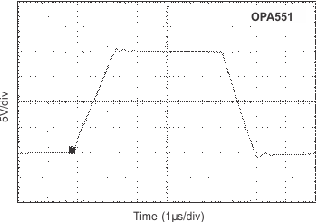
| SR | Slew rate | G = 1 | ±15 | V/µs | |||
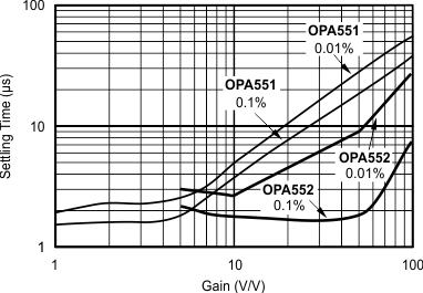
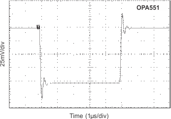
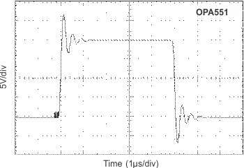
| Settling time | 0.1% | G = 1, CL = 100 pF, 10-V Step | 1.3 | µs | |||
| 0.01% | G = 1, CL = 100 pF, 10-V Step | 2 | |||||
| THD+N | Total harmonic distortion + noise | f = 1 kHz, VO = 15 VRMS, RL = 3 kΩ, G = 3 |
0.0005% | ||||
| f = 1 kHz, VO = 15 VRMS, RL = 300 kΩ, G = 3 |
0.0005% | ||||||
| Overload recovery time | VIN × Gain = VS | 1 | µs | ||||
| OPA552 FREQUENCY RESPONSE | |||||||
| GBW | Gain-bandwidth product | 12 | MHz | ||||
| SR | Slew rate | G = 5 | ±24 | V/µs | |||
| Settling time | 0.1% | G = 5, CL = 100 pF, 10-V Step | 2.2 | µs | |||
| 0.01% | G = 5, CL = 100 pF, 10-V Step | 3 | |||||
| THD+N | Total harmonic distortion + noise | f = 1 kHz, VO = 15 VRMS, RL = 3 kΩ, G = 5 |
0.0005% | ||||
| f = 1 kHz, VO = 15 VRMS, RL = 300 kΩ, G = 5 |
0.0005% | ||||||
| Overload recovery time | VIN × Gain = VS | 1 | µs | ||||
| OUTPUT | |||||||
| VOUT | Voltage output | IO = 200 mA | (V–) + 3 | (V+) – 3 | V | ||
| IO = 200 mA TJ = –40°C to 125°C |
(V–) + 3.5 | (V+) – 3.5 | |||||
| IO = 10 mA | (V–) + 2 | (V+) – 2 | |||||
| IO = 10 mA TJ = –40°C to 125°C |
(V–) + 2.5 | (V+) – 2.7 | |||||
| IO | Maximum continuous current output: DC | Package dependent — see Power Dissipation section | ±200 | mA | |||
| ISC | Short-circuit current | ±380 | mA | ||||
| CLOAD | Capacitive load drive | Stable operation | See Figure 19 | ||||
| SHUTDOWN FLAG | |||||||
| Thermal shutdown status output | Normal operation, sourcing | 0.05 | 1 | µA | |||
| Thermal shutdown, sourcing | 80 | 120 | 160 | ||||
| Voltage compliance range | V– | (V+) –1.5 | V | ||||
| Junction temperature | Shutdown | 160 | °C | ||||
| Reset from shutdown | 140 | ||||||
| POWER SUPPLY | |||||||
| VS | Specified voltage | ±30 | V | ||||
| Operating voltage range | ±4 | ±30 | V | ||||
| IQ | Quiescent current | IO = 0 mA | ±7 | ±8.5 | mA | ||
| TJ = –40°C to 125°C | ±10 | ||||||
| TEMPERATURE RANGE | |||||||
| TJ | Specified range | –40 | 125 | °C | |||
| Operating range | –55 | 125 | |||||
6.6 Typical Characteristics
At TJ = 25°C, VS = ±30 V and RL = 3 kΩ, unless otherwise noted.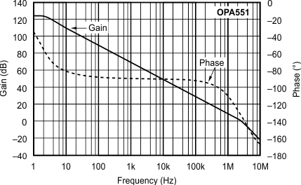
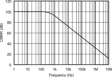
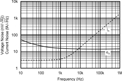
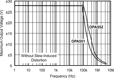
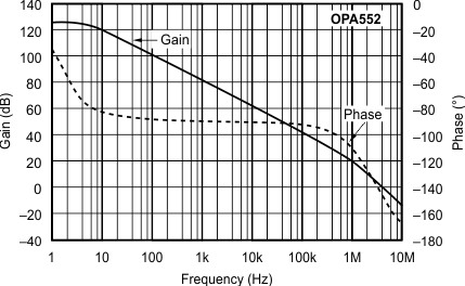
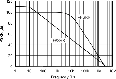
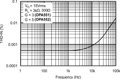
vs Frequency
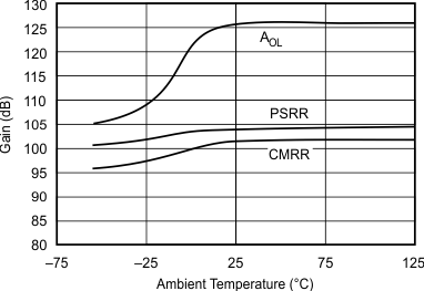
and Common-Mode Rejection Ratio vs Temperature
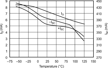
vs Temperature
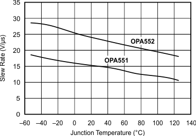
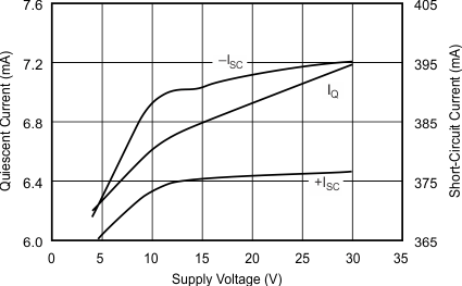
vs Supply Voltage
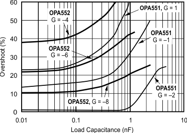
vs Load Capacitance
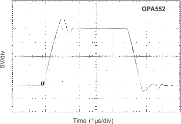
| G = 1, CL = 100 pF |
OPA552
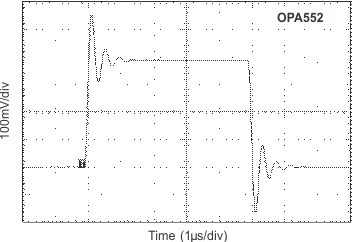
| G = 1, CL = 100 pF |
OPA552
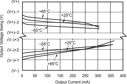
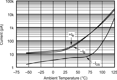
vs Temperature

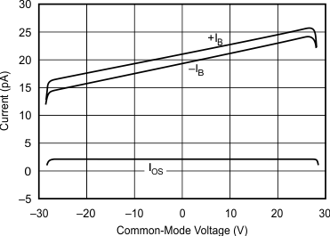
vs Common-Mode Voltage
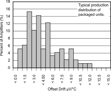
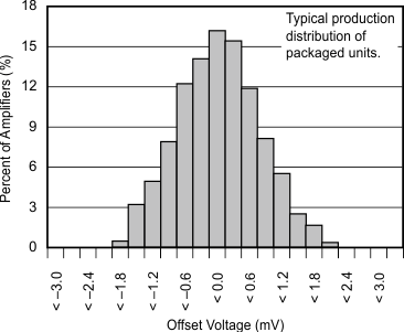 Figure 16. Offset Voltage Production Distribution
| G = 1, CL = 100 pF | ||
OPA551
| G = 1, CL = 100 pF |
OPA551
| G = 1, CL = 1000 pF |
OPA551