-
SN65HVS883 24 V, Eight-Channel Digital-Input Serializer
- 1 Features
- 2 Applications
- 3 Description
- 4 Revision History
- 5 Pin Configuration and Functions
- 6 Specifications
- 7 Parameter Measurement Information
- 8 Detailed Description
- 9 Application and Implementation
- 10Power Supply Recommendations
- 11Layout
- 12Device and Documentation Support
- 13Mechanical, Packaging, and Orderable Information
- IMPORTANT NOTICE
Package Options
Mechanical Data (Package|Pins)
- PWP|28
Thermal pad, mechanical data (Package|Pins)
Orderable Information
SN65HVS883 24 V, Eight-Channel Digital-Input Serializer
1 Features
- Eight Sensor Inputs
- High Input Voltage up to 34 V
- Selectable Debounce Filters
From 0 ms to 3 ms - Adjustable Current Limits
From 0.2 mA to 5.2 mA - Field Inputs and Supply Lines Protected
to 15-kV HBM
- Output Drivers for External Status LEDs
- Cascadable for More Inputs in Multiples of Eight
- SPI-Compatible Interface
- Regulated 5-V Output for External Digital Isolator
- Low-Supply Voltage Indicator
2 Applications
- Sensor Inputs for Industrial Automation and Process Control
- IEC61131-2 Type 1, 2, or 3 Switches
- EN60947-5-2 Proximity Switches
- High Channel Count Digital Input Modules for PC and PLC Systems
- Decentralized I/O Modules
3 Description
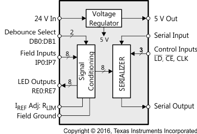
The SN65HVS883 is a 24-V, eight-channel, digital-input serializer for high-channel density digital input modules of PC and PLC-based systems in industrial automation. In combination with galvanic isolators, the device completes the interface between the 24-V sensor outputs of the field-side and the low-voltage controller inputs at the control-side. Input signals provided by EN60947-5-2 compliant 2-wire and
3-wire proximity switches are current-limited and then validated by internal debounce filters. The input switching characteristic is in accordance with IEC61131-2 for Type 1, 2, and 3 sensor switches.
Upon the application of load and clock signals, input data is latched in parallel into the shift register and afterwards clocked out serially via a subsequent isolator into a serial PLC input.
Cascading of multiple SN65HVS883 is possible by connecting the serial output of the leading device with the serial input of the following device, enabling the design of high-channel count input modules. Input status is indicated via 3-mA constant current LED outputs. An external precision resistor is required to set the internal reference current. The integrated voltage regulator provides a 5-V output to supply low-power isolators. An internal supply voltage monitor provides a chip-okay (CHOK) indication.
The SN65HVS883 comes in a 28-pin PWP PowerPAD™ package allowing for efficient heat dissipation. The device is specified for operation at temperatures from –40°C to 85°C.
Device Information(1)
| PART NUMBER | PACKAGE | BODY SIZE (NOM) |
|---|---|---|
| SN65HVS883 | HTSSOP (28) | 9.70 mm x 4.40 mm |
- For all available packages, see the orderable addendum at the end of the data sheet.
Simplified I/O Structure
4 Revision History
| DATE | REVISION | NOTES |
|---|---|---|
| September 2016 | * | Initial release. |
5 Pin Configuration and Functions
Pin Functions
| PIN | DESCRIPTION | |
|---|---|---|
| PIN NO. | NAME | |
| 1, 2 | DB0, DB1 | Debounce select inputs |
| 3, 5, 7, 9, 11, 18, 20, 22 |
IPx | Input channel x |
| 4, 6, 8, 10, 12, 17, 19, 21 |
REx | Return path x (LED drive) |
| 13 | RLIM | Current limiting resistor |
| 14 | V24 | 24 VDC field supply |
| 15 | 5VOP | 5 V output to supply low-power isolators |
| 16 | CHOK | Chip okay indicator output |
| 23 | SOP | Serial data output |
| 24 | CE | Clock enable input |
| 25 | CLK | Serial clock input |
| 26 | LD | Load pulse input |
| 27 | SIP | Serial data input |
| 28 | FGND | Field ground |
6 Specifications
6.1 Absolute Maximum Ratings
over operating free-air temperature range (unless otherwise noted)| MIN | MAX | UNIT | ||||
|---|---|---|---|---|---|---|
| V24 | Field power input | V24 | –0.3 | 36 | V | |
| VIPx | Field digital inputs | IPx | –0.3 | 36 | V | |
| VID | Voltage at any logic input | DB0, DB1, CLK, SIP, CE, LD | –0.5 | 6 | V | |
| IO | Output current | CHOK, SOP | ±8 | mA | ||
| PTOT | Continuous total power dissipation | See Thermal Information table | ||||
| TJ | Junction temperature | 170 | °C | |||
6.2 ESD Ratings
| VALUE | UNIT | ||||
|---|---|---|---|---|---|
| V(ESD) | Electrostatic discharge | Human-body model (HBM), per ANSI/ESDA/JEDEC JS-001(1) | All pins | ±4000 | V |
| IPx,V24 | ±15000 | ||||
| Charged-device model (CDM), per JEDEC specification JESD22-C101(2) | All pins | ±1000 | |||
| Machine Mode(3) | All pins | ±100 | |||
6.3 Recommended Operating Conditions
| MIN | TYP | MAX | UNIT | ||
|---|---|---|---|---|---|
| V24 | Field supply voltage | 10 | 24 | 34 | V |
| VIPL | Field input low-state input voltage(1) | 0 | 4 | V | |
| VIPH | Field input high-state input voltage(1) | 10 | 34 | V | |
| VIL | Logic low-state input voltage | 0 | 0.8 | V | |
| VIH | Logic high-state input voltage | 2 | 5.5 | V | |
| RLIM | Current limiter resistor | 17 | 25 | 500 | kΩ |
| fIP | Input data rate(2) | 0 | 1 | Mbps | |
| TJ | 150 | °C | |||
| TA | –40 | 85 | °C | ||
6.4 Thermal Information
| THERMAL METRIC(1) | SN65HVS883 | UNIT | ||
|---|---|---|---|---|
| PWP (HTSSOP) | ||||
| 28 PINS | ||||
| RθJA | Junction-to-ambient thermal resistance | 35 | °C/W | |
| RθJC(top) | Junction-to-case (top) thermal resistance | 4.27 | °C/W | |
| RθJB | Junction-to-board thermal resistance | 15 | °C/W | |
| PD | Device power dissipation | ILOAD = 50 mA, RIN = 0, IPO–IP7 = V24 = 30 V, RE7 = FGND, fCLK = 100 MHz, IIP-LIM and ICC = worst case with RLIM = 25 kΩ |
2591 | mW |
6.5 Electrical Characteristics
all voltages measured against FGND unless otherwise stated, see Figure 12| SYMBOL | PARAMETER | PIN | TEST CONDITIONS | MIN | TYP | MAX | UNIT |
|---|---|---|---|---|---|---|---|
| VTH–(IP) | Low-level device input threshold voltage | IP0–IP7 | 18 V< V24 < 34 V, RIN = 0 Ω , RLIM = 25 kΩ |
4 | 4.3 | V | |
| VTH+(IP) | High-level device input threshold voltage | 5.2 | 5.5 | V | |||
| VHYS(IP) | Device input hysteresis | 0.9 | V | ||||
| VTH–(IN) | Low-level field input threshold voltage | measured at field side of RIN |
18 V < V24 < 34 V, RIN = 1.2 kΩ ± 5%, RLIM = 25 kΩ |
6 | 8.4 | V | |
| VTH+(IN) | High-level field input threshold voltage | 9.4 | 10 | V | |||
| VHYS(IN) | Field input hysteresis | 1 | V | ||||
| VTH–(V24) | Low-level V24-monitor threshold voltage | V24 | 15 | 16.05 | V | ||
| VTH+(V24) | High-level V24-monitor threshold voltage | 16.8 | 18 | V | |||
| VHYS(V24) | V24-monitor hysteresis | 0.75 | V | ||||
| RIP | Input resistance | IP0–IP7 | 3 V < VIPx < 6 V, RIN = 1.2 kΩ ± 5%, RLIM = 25 kΩ |
1.4 | 1.83 | 2.3 | kΩ |
| IIP-LIM | Input current limit | 10 V < VIPx < 34 V, RLIM = 25 kΩ |
3.15 | 3.6 | 4 | mA | |
| VOL | Logic low-level output voltage | SOP, CHOK | IOL = 20 μA | 0.4 | V | ||
| VOH | Logic high-level output voltage | IOH = –20 μA | 4 | V | |||
| IIL | Logic input leakage current | DB0, DB1, SIP, LD, CE, CLK |
–50 | 50 | μA | ||
| IRE-on | RE on-state current | RE0–RE7 | RLIM = 25 kΩ, REX = FGND |
2.8 | 3.15 | 3.5 | mA |
| ICC(V24) | Supply current | V24 | IP0 to IP7 = V24, 5VOP = open, REX = FGND, All logic inputs open |
8.7 | mA | ||
| VO(5V) | Linear regulator output voltage | 5VOP | 18 V < V24 < 34 V, no load |
4.5 | 5 | 5.5 | V |
| 18 V < V24 < 34 V, IL = 50 mA |
4.5 | 5 | 5.5 | ||||
| ILIM(5V) | Linear regulator output current limit | 115 | mA | ||||
| ΔV5/ΔV24 | Line regulation | 5VOP, V24 | 18 V < V24 < 34 V, IL = 5 mA |
2 | mV/V | ||
| tDB | Debounce times of input channels | IP0–IP7 | DB0 = open, DB1 = FGND |
0 | ms | ||
| DB0 = FGND, DB1 = open |
1 | ||||||
| DB0 = DB1 = open | 3 | ||||||
| tDB-HL | Voltage monitor debounce time after V24 < 15 V (CHOK turns low) | V24, CHOK | 1 | ms | |||
| tDB-LH | Voltage monitor debounce time after V24 > 18 V (CHOK turns high) | 6 | ms | ||||
| TSHDN | Shutdown temperature | 170 | °C |
6.6 Timing Requirements
over operating free-air temperature range (unless otherwise noted)| SYMBOL | PARAMETER | MIN | TYP | MAX | UNIT | |
|---|---|---|---|---|---|---|
| tW1 | CLK pulse width | See Figure 9 | 4 | ns | ||
| tW2 | LD pulse width | See Figure 7 | 6 | ns | ||
| tSU1 | SIP to CLK setup time | See Figure 10 | 4 | ns | ||
| tH1 | SIP to CLK hold time | See Figure 10 | 2 | ns | ||
| tSU2 | Falling edge to rising edge (CE to CLK) setup time | See Figure 11 | 4 | ns | ||
| tREC | LD to CLK recovery time | See Figure 8 | 2 | ns | ||
| fCLK | Clock pulse frequency (50% duty cycle) | See Figure 9 | DC | 100 | MHz | |
6.7 Switching Characteristics
over operating free-air temperature range (unless otherwise noted)| SYMBOL | PARAMETER | TEST CONDITIONS | MIN | TYP | MAX | UNIT |
|---|---|---|---|---|---|---|
| tPLH1, tPHL1 | CLK to SOP | CL = 15 pF, see Figure 9 | 10 | ns | ||
| tPLH2, tPHL2 | LD to SOP | CL = 15 pF, see Figure 7 | 14 | ns | ||
| tr, tf | Rise and fall times | CL = 15 pF, see Figure 9 | 5 | ns |
6.8 Typical Input Characteristics
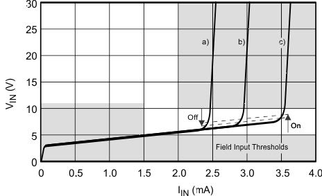
| RIN = 1.2 kΩ | a) IIP-LIM = 2.5 mA (RLIM = 36.1 kΩ) | |||
| b) IIP-LIM = 3.0 mA (RLIM = 30.1 kΩ) | ||||
| c) IIP-LIM = 3.6 mA (RLIM = 24.9 kΩ) | ||||
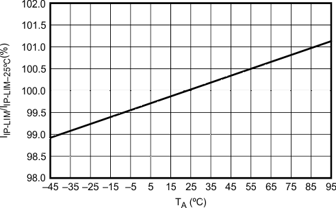
| V24 = 24 V | VIN = 24 V | RIN = 1.2 kΩ |
| RLIM = 24.9 kΩ |
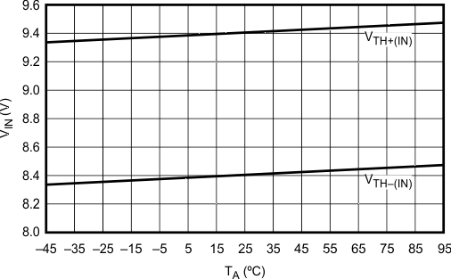
| V24 = 24 V | RIN = 1.2 kΩ | RLIM = 24.9 kΩ |
6.9 Typical Voltage Regulator Performance Characteristics
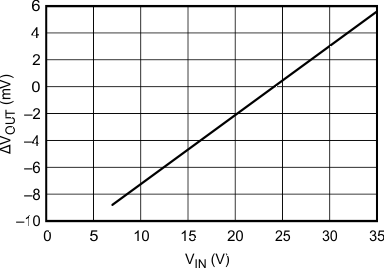
| ILOAD = 5 mA | TA = 27°C | |
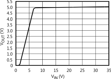
| RLOAD = 100 Ω | ||
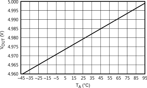
| ILOAD = 0 mA | ||
7 Parameter Measurement Information
7.1 Waveforms
For the complete serial interface timing, refer to Figure 21.

 Figure 9. Serial – Shift Mode


7.2 Signal Conventions
 Figure 12. On/Off Threshold Voltage Measurements
8 Detailed Description
8.1 Overview
The SN65HVS883 is an 8 channel, digital input serializer which operates from a 24 V supply and accepts digital inputs of up to 34 V on the 8 channels (IP0-IP7). The device provides a serially shifted digital output with reduced voltage ranges of 0-5 V for applications in industrial and building automation systems. The SN65HVS883 meets JEDEC standards for ESD protection (refer to ESD Ratings), and is SPI compatible for interfacing with standard microcontrollers. The serializer operates in 2 fundamental modes: Load Mode and Shift mode. In Load mode, information from the field inputs is allowed to latch into the shift register. In Shift mode, the information stored in the parallel shift register can be serially shifted to the serial output (SOP). A detailed description of the functional modes is available in the Device Functional Modes section.
8.2 Functional Block Diagram

8.3 Feature Description
8.3.1 Digital Inputs
Each digital input operates as a controlled current sink limiting the input current to a maximum value of ILIM. The current limit is derived from the reference current via ILIM = n × IREF, and IREF is determined by IREF = VREF/RLIM. Thus, changing the current limit requires the change of RLIM to a different value via: RLIM = n × VREF/ILIM.
Inserting the actual values for n and VREF gives: RLIM = 90 V / ILIM.
While the device is specified for a current limit of 3.6 mA, (via RLIM = 25 kΩ), it is easy to lower the current limit to further reduce the power consumption. For example, for a current limit of 2.5 mA simply calculate:

 Figure 13. Digital Input Stage
8.3.2 Debounce Filter
The HVS883 applies a simple analog/digital filtering technique to remove unintended signal transitions due to contact bounce or other mechanical effects. Any new input (either low or high) must be present for the duration of the selected debounce time to be latched into the shift register as a valid state.
The logic signal levels at the control inputs, DB0 and DB1 of the internal Debounce-Select logic determine the different debounce times listed in the following truth table.
Table 1. Debounce Times
| DB1 | DB0 | FUNCTION | |
|---|---|---|---|
| Open | Open | 3 ms delay | |
| Open | FGND | 1 ms delay | |
| FGND | Open | 0 ms delay (Filter bypassed) |
|
| FGND | FGND | Reserved |
 Figure 14. Equivalent Input Diagram
8.3.3 Shift Register
The conversion from parallel input to serial output data is performed by an eight-channel, parallel-in serial-out shift register. Parallel-in access is provided by the internal inputs, PIP0–PIP7, that are enabled by a low level at the load input (LD). When clocked, the latched input data shift towards the serial output (SOP). The shift register also provides a clock-enable function.
Clocking is accomplished by a low-to-high transition of the clock (CLK) input while LD is held high and the clock enable (CE) input is held low for all registers in the shift register except the last register which is latched by a high-to-low transition. Parallel loading is inhibited when LD is held high. The parallel inputs to the register are enabled while LD is low independently of the levels of the CLK, CE, or serial (SIP) inputs.
 Figure 15. Shift Register Logic Structure
8.3.4 Voltage Regulator
The on-chip linear voltage regulator provides a 5 V supply to the internal- and external circuitry, such as digital isolators, with an output drive capability of 50 mA and a typical current limit of 115 mA. The regulator accepts input voltages from 34 V down to 10 V. Because the regulator output is intended to supply external digital isolator circuits proper output voltage decoupling is required. For best results connect a 1 μF and a 0.1 μF ceramic capacitor as close as possible to the 5VOP-output. For longer traces between the SN65HVS883 and isolators of the ISO72xx family use additional 0.1 μF and 10 pF capacitors next to the isolator supply pins. Make sure, however, that the total load capacitance does not exceed 4.7 μF.
For good stability the voltage regulator requires a minimum load current, IL-MIN. Ensure that under any operating condition the ratio of the minimum load current in mA to the total load capacitance in μF is larger than 1:

8.3.5 Supply Voltage Monitor
The integrated supply voltage monitor senses the supply voltage of the SN65HVS883 at the V24-pin. If this voltage drops below 15 V but stays within the regulator’s operating range, i.e., 15 V > V24 > 10 V, the output CHOK goes low 1 ms later. When the supply voltage returns to 24 V, the CHOK output turns logic high after
6 ms. Should the supply voltage drop below 10 V, the device ceases operation. Upon the supply returning to above 18 V, the CHOK output turns high again after 6 ms.
 Figure 16. CHOK Output Timing as a Function of Supply Voltage Drop at V24
8.4 Device Functional Modes
The 2 functional modes of operation are Load mode and Shift mode.
Load mode enables information from the field inputs to latch into the shift register. To enter load mode, the LD pin must be held low, and the device remains in load mode regardless of the CLK, CE, or serial (SIP) input levels. A high level at the LD pin switches the device into Shift mode.
When the device is in Shift mode, a low level at the CE pin causes the data stored in all registers of the parallel shift register except for the last register, to be serially shifted toward the serial output (SOP) on the rising edge of CLK. The final register in the shift register will be shifted toward the serial output (SOP) on the falling edge of CLK. A high level at the CE pin inhibits the serial shifting, which is demonstrated in Figure 21. After 8 consecutive CLK cycles, the serial output (SOP) remains at the level of the serial input (SIP) which is internally pulled to logic high. A logic high at the CE pin is required to signify the end of the serial data output. For of a daisy chained configuration, the serial output (SOP) of the SN65HVS883 can be connected to the serial input (SIP) of a following device, and additional clock cycles are required to shift the additional data out of the chain. The number of consecutive clock cycles will equal 8 times the number of devices in the chain. See Figure 22 for an example of a cascaded chain of 4x SN65HVS883.
9 Application and Implementation
NOTE
Information in the following applications sections is not part of the TI component specification, and TI does not warrant its accuracy or completeness. TI’s customers are responsible for determining suitability of components for their purposes. Customers should validate and test their design implementation to confirm system functionality.
9.1 Application Information
9.1.1 System-Level EMC
The SN65HVS883 must operate reliably in harsh industrial environments. At a system level, the device is tested according to several international electromagnetic compatibility (EMC) standards.
In addition to the device internal ESD structures, external protection circuitry, such as the one in Figure 17, can be used to absorb as much energy from burst- and surge-transients as possible.
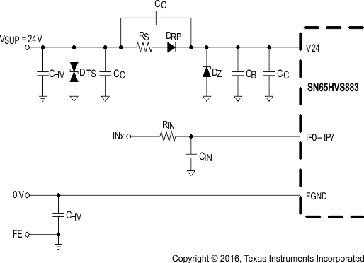 Figure 17. Typical EMC Protection Circuitry for Supply and Signal Inputs
Table 3. Components
| DESIGNATOR | DESCRIPTION |
|---|---|
| DTS | 39 V Transient Voltage Suppressor: SM15T39CA |
| DRP | Super Rectifier: BYM10-1000, or General Purpose rectifier: 1N4007 |
| DZ | 33 V – 36 V fast Zener Diode, Z2SMB36 |
| RS | 56 Ω, 1/3 W MELF Resistor |
| RIN | 1.2 kΩ, 1/4 W MELF Resistor |
| CIN | 22 nF, 60 V Ceramic Capacitor |
| CHV | 4.7 nF, 2 kV Ceramic Capacitor |
| CC | n x 220 nF, 60 V Ceramic Capacitors |
| CB | 1 µF - 10 µF, 60 V Ceramic Capacitor |
9.1.2 Input Channel Switching Characteristics
The input stage of the SN65HVS883 is so designed, that for an input resistor RIN = 1.2 kΩ the trip point for signalling an ON-condition is at 9.4 V at 3.6 mA. This trip point satisfies the switching requirements of IEC61131-2 Type 1 and Type 3 switches.
 Figure 18. Switching Characteristics for IEC61131-2 Type 1, 2, and 3 Proximity Switches
For a Type 2 switch application, two inputs are connected in parallel. The current limiters then add to a total maximum current of 7.2 mA. While the return-path (RE-pin), of one input might be used to drive an indicator LED, the RE-pin of the other input channel should be connected to ground (FGND).
Paralleling input channels reduces the number of available input channels from an octal Type 1 or Type 3 input to a quad Type 2 input device. Note, that in this configuration output data of an input channel is represented by two shift register bits.
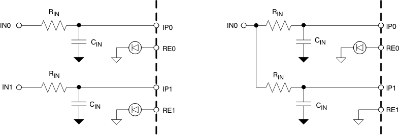 Figure 19. Paralleling Two Type 1 or Type 3 Inputs Into One Type 2 Input
9.1.3 Digital Interface Timing
The digital interface of the SN65HVS883 is SPI compatible and interfaces, isolated or non-isolated, to a wide variety of standard micro controllers.
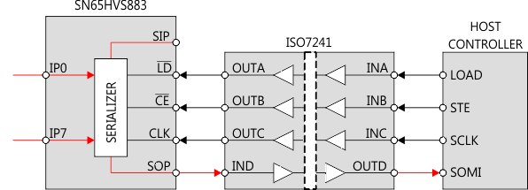 Figure 20. Simple Isolation of the Shift Register Interface
Upon a low-level at the load input, LD, the information of the field inputs, IP0 to IP7 is latched into the shift register. Taking LD high again blocks the parallel inputs of the shift register from the field inputs. A low-level at the clock-enable input, CE, enables the clock signal, CLK, to serially shift the data to the serial output, SOP. Data is clocked into the shift register at the rising edge of CLK and out of the shift register on the falling edge of CLK. Thus after eight consecutive clock cycles all field input data have been clocked out of the shift register and the information of the serial input, SIP, appears at the serial output, SOP.
The CE signal should only be transitioned low while the CLK signal is low which ensures that a rising edge of CLK occurs before a falling edge of CLK. This shifts the data into and through the shift register up until the final register before the first bit that was loaded into the final register is shifted out the serial output, SOP. If a falling edge of CLK is seen first following the transition of CE to low, the final register outputs the first bit, IP0, on the serial output, SOP, before shifting the rest of the bits through the shift register. The previous value of the second to last register prior to the LD event will then be shifted into the final register on the next rising CLK edge and output on the serial output, SOP, before the next valid bit, IP1, is output on the serial output, SOP. This appears as an erroneous bit in the serial data. Also, depending on how many falling CLK edges were seen before the CE signal is transitioned back high, the final bit, IP7, may not get shifted out of the shift register.
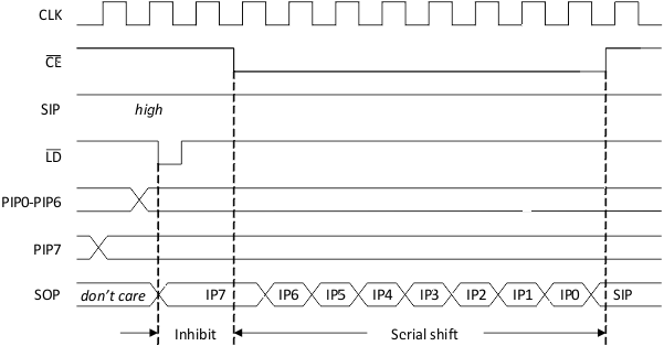 Figure 21. Interface Timing for Parallel-Load and Serial-Shift Operation of the Shift Register
9.1.4 Cascading for High Channel Count Input Modules
Designing high-channel count modules require cascading multiple SN65HVS883 devices. Simply connect the serial output (SOP) of a leading device with the serial input (SIP) of a following device without changing the processor interface.
 Figure 22. Cascading Four SN65HVS883 for a 32-Channel Input Module
NOTE
When daisy-chaining multiple devices, the maximum operating rate (CLK pulse width) may need to be restricted in order to maintain minimum set-up/hold timing relationships between the serial data (SIP/SOP) and the CLK line.
9.2 Typical Application
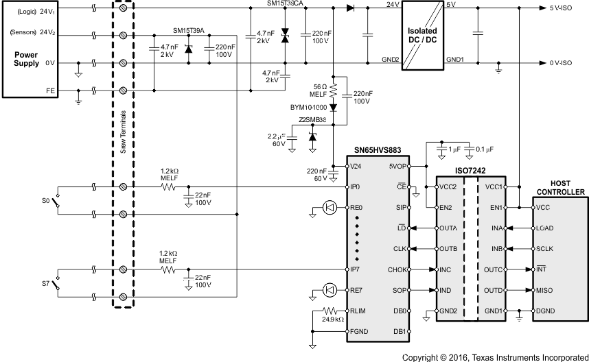 Figure 23. Typical Digital Input Module Application
9.2.1 Design Requirements
The simplified schematic in Figure 23 demonstrates a typical application of the SN65HVS883 for sensing the state of digital switches with 24-V high logic levels. In this application, a 5-V host controller must receive the state of 8 switches as a serial input, while remaining isolated from the high voltage power supply.
9.2.2 Detailed Design Procedure
9.2.2.1 Input Stage
Selection of the current limiting resistor RLIM sets the input current limit ILIM for the device. Digital Inputs includes necessary equations for choosing the limiting resistor.
The On/Off voltage thresholds at the device pin VTH(IP+) and VTH(IP-) are fixed to 5.2 V and 4.3 V respectively, however the On/Off voltage thresholds of the field input VTH(IN+) and VTH(IN-) are determined by the value of the series resistor RIN placed between the field input and the device. The threshold voltage VTH(IN+) is determined with the following equation:

Substituting Equation 1 and solving for RIN produces an equation for RIN given a desired on-threshold.

The following equation can be used to calculate the off-threshold voltage given a value for RIN

Figure 24 contains an example input characteristic:
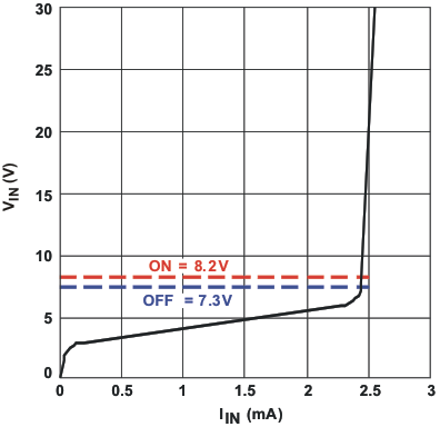 Figure 24. SN65HVS883 Example Input Characteristic
9.2.2.2 Setting Debounce Time
The logic signals at the DB0 and DB1 pins determine the denounce times for the device according to the table in section 6.5. The DB0 and DB1 pins are internally pulled high. Connecting the pins to GND in different configurations allows for selection of 0, 1, or 3 ms debounce times. In noisy environments, it is recommended that unused DB pins should be connected externally to a 5 V supply.
9.2.2.3 Example: High-Voltage Sensing Application
For the high-voltage sensing application in Figure 23, inputs from each switch (S0-S7) are connected to the 8 parallel inputs (IP0-IP7) of the SN65HVS883 through 1.2 kΩ MELF resistors. Small capacitors (22 nF) are tied to ground at each input to provide noise protection for the signals. A resistor is added between the RLIM pin and GND to provide a device current limit according to the equation ILIM = 90 V / RLIM. In this example, with a 24.9 kΩ resistor, the current limit for the device is set to 3.6 mA. LEDs are placed between pins RE0-RE7 to allow for external status observation of the parallel inputs. Finally the SN65HVS883 is connected through a digital isolation device to the host controller to provide galvanic isolation to the external interfaces and to allow for communication between the 5 V SN65HVS883 logic and the 5-V host controller. The host controller manages mode switching and clocking of the SN65HVS883 through the digital isolation device.
9.2.3 Application Curve
The application traces acquired in Figure 25 demonstrates the typical behavior of the SN65HVD883 when in shift mode (Load Pulse Input pulled high and Clock Enable Input pulled low). Channel 1 shows the SIP input, Channel 2 shows the CLK input, and Channel 3 shows the SOP output.
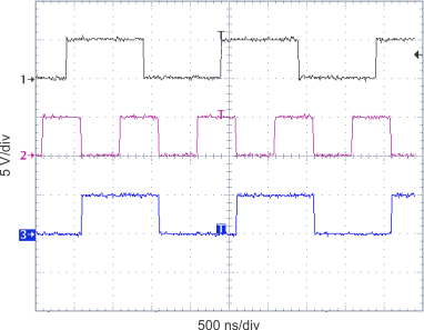 Figure 25. SN65HVS883 Serial Input and Output Timing
10 Power Supply Recommendations
The SN65HVS883 operates within a recommended supply voltage range from 4.5 V to 5.5 V. A 0.1 µF or larger capacitor should be placed between VCC and ground to improve power supply noise immunity. A current limiting resistor can be used to reduce overall power consumption as described in Digital Inputs. The high voltage parallel field inputs can accept voltages ranging from 0 V to 34 V, however all other inputs must remain between 0 V to 5 V. Refer to the Recommended Operating Conditions table for more detailed voltage suggestions. High voltage field inputs should be buffered as shown in Figure 23 to improve input noise immunity.
11 Layout
11.1 Layout Guidelines
- Place series MELF resistors between the field inputs and the device input pins.
- Place small ~22 nF capacitors close to the field input pins to reduce noise.
- Place a supply buffering 0.1-µF capacitor around as close to the VCC pin as possible.
11.2 Layout Example

12 Device and Documentation Support
12.1 Third-Party Products Disclaimer
TI'S PUBLICATION OF INFORMATION REGARDING THIRD-PARTY PRODUCTS OR SERVICES DOES NOT CONSTITUTE AN ENDORSEMENT REGARDING THE SUITABILITY OF SUCH PRODUCTS OR SERVICES OR A WARRANTY, REPRESENTATION OR ENDORSEMENT OF SUCH PRODUCTS OR SERVICES, EITHER ALONE OR IN COMBINATION WITH ANY TI PRODUCT OR SERVICE.
12.2 Receiving Notification of Documentation Updates
To receive notification of documentation updates, navigate to the device product folder on ti.com. In the upper right corner, click on Alert me to register and receive a weekly digest of any product information that has changed. For change details, review the revision history included in any revised document.
12.3 Community Resources
The following links connect to TI community resources. Linked contents are provided "AS IS" by the respective contributors. They do not constitute TI specifications and do not necessarily reflect TI's views; see TI's Terms of Use.
-
TI E2E™ Online Community TI's Engineer-to-Engineer (E2E) Community. Created to foster collaboration among engineers. At e2e.ti.com, you can ask questions, share knowledge, explore ideas and help solve problems with fellow engineers.
-
Design Support TI's Design Support Quickly find helpful E2E forums along with design support tools and contact information for technical support.
12.4 Trademarks
PowerPAD, E2E are trademarks of Texas Instruments.
All other trademarks are the property of their respective owners.
12.5 Electrostatic Discharge Caution

These devices have limited built-in ESD protection. The leads should be shorted together or the device placed in conductive foam during storage or handling to prevent electrostatic damage to the MOS gates.
12.6 Glossary
SLYZ022 — TI Glossary.
This glossary lists and explains terms, acronyms, and definitions.