-
THS452x Very Low Power, Negative Rail Input, Rail-To-Rail Output, Fully Differential Amplifier
- 1 Features
- 2 Applications
- 3 Description
- 4 Revision History
- 5 Device Comparison Table
- 6 Pin Configuration and Functions
-
7 Specifications
- 7.1 Absolute Maximum Ratings
- 7.2 ESD Ratings
- 7.3 Recommended Operating Conditions
- 7.4 Thermal Information
- 7.5 Electrical Characteristics: VS+ - VS- = 3.3 V
- 7.6 Electrical Characteristics: VS+ - VS- = 5 V
- 7.7 Typical Characteristics
- 7.8 Typical Characteristics: VS+ - VS- = 3.3 V
- 7.9 Typical Characteristics: 5 V
-
8 Detailed Description
- 8.1 Overview
- 8.2 Functional Block Diagram
- 8.3
Feature Description
- 8.3.1 Frequency Response
- 8.3.2 Distortion
- 8.3.3 Slew Rate, Transient Response, Settling Time, Output Impedance, Overdrive, Output Voltage, and Turn-On/Turn-Off Time
- 8.3.4 Common-Mode and Power-Supply Rejection
- 8.3.5 VOCM Input
- 8.3.6 Typical Performance Variation With Supply VoltageTypical Performance Variation with Supply Voltage section
- 8.3.7 title of Single-Supply Operation sectionSingle-Supply Operation
- 8.3.8 Low-Power Applications and the Effects of Resistor Values on Bandwidth
- 8.3.9 Frequency Response Variation due to Package Options
- 8.3.10 Driving Capacitive Loads
- 8.3.11 Audio Performance
- 8.3.12 Audio On/Off Pop Performance
- 8.4
Device Functional Modes
- 8.4.1
Operation from Single-Ended Sources to Differential Outputs
- 8.4.1.1 AC-Coupled Signal Path Considerations for Single-Ended Input to Differential Output Conversion
- 8.4.1.2 DC-Coupled Input Signal Path Considerations for Single-Ended to Differential Conversion
- 8.4.1.3 Resistor Design Equations for the Single-Ended to Differential Configuration of the FDA
- 8.4.1.4 Input Impedance for the Single-Ended to Differential FDA Configuration
- 8.4.2 Differential-Input to Differential-Output Operation
- 8.4.1
Operation from Single-Ended Sources to Differential Outputs
- 8.5 Programming
-
9 Application and Implementation
- 9.1 Application Information
- 9.2 Typical Applications
- 10Power Supply Recommendations
- 11Layout
- 12Device and Documentation Support
- 13Mechanical, Packaging, and Orderable Information
- IMPORTANT NOTICE
Package Options
Mechanical Data (Package|Pins)
Thermal pad, mechanical data (Package|Pins)
Orderable Information
THS452x Very Low Power, Negative Rail Input, Rail-To-Rail Output, Fully Differential Amplifier
1 Features
- Fully Differential Architecture
- Bandwidth: 145 MHz (AV = 1 V/V)
- Slew Rate: 490 V/μs
- HD2: –133 dBc at 10 kHz (1 VRMS, RL = 1 kΩ)
- HD3: –141 dBc at 10 kHz (1 VRMS, RL = 1 kΩ)
- Input Voltage Noise: 4.6 nV/√Hz (f = 100 kHz)
- THD+N: –112dBc (0.00025%) at 1 kHz (22-kHz BW, G = 1, 5 VPP)
- Open-Loop Gain: 119 dB (DC)
- NRI—Negative Rail Input
- RRO—Rail-to-Rail Output
- Output Common-Mode Control (with Low Offset)
- Power Supply:
- Power-Down Capability: 20 μA (typical)
2 Applications
3 Description
The THS4521, THS4522, and THS4524 family of devices are very low-power, fully differential amplifiers with rail-to-rail output and an input common-mode range that includes the negative rail. These amplifiers are designed for low-power data acquisition systems and high-density applications where power dissipation is a critical parameter, and provide exceptional performance in audio applications.
The family includes single FDA (THS4521), dual FDA (THS4522), and quad FDA (THS4524) versions.
Device Information(1)
| PART NUMBER | PACKAGE | BODY SIZE (NOM) |
|---|---|---|
| THS4521 | SOIC (8) | 4.90 mm × 3.91 mm |
| VSSOP (8) | 3.00 mm × 3.00 mm | |
| THS4522 | TSSOP (16) | 5.00 mm × 4.40 mm |
| THS4524 | TSSOP (38) | 9.70 mm × 4.40 mm |
- For all available packages, see the package option addendum at the end of the datasheet.
4 Revision History
Changes from G Revision (December 2014) to H Revision
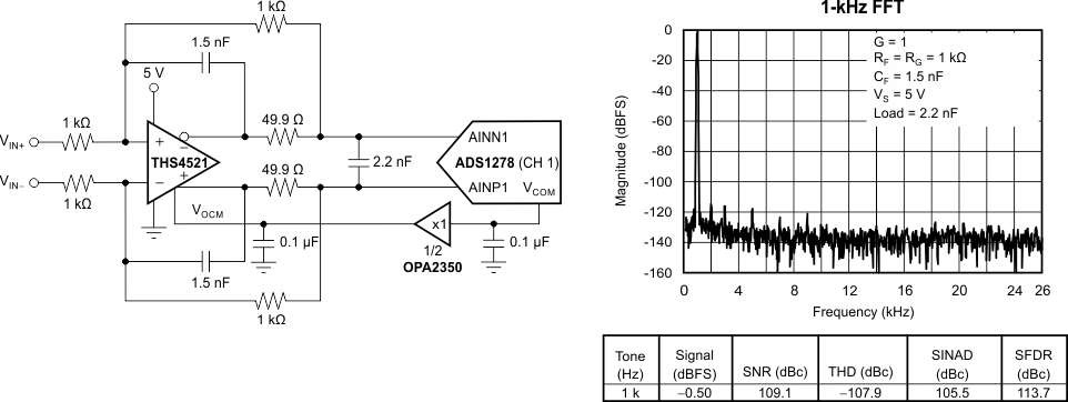
- Changed capacitor units in front page diagram from mF to µF (typo)Go
- Changed RF and RG unit in front page FFT plot from kW to kΩ (typo)Go
- Changed Absolute Maximum Ratings minimum storage temperature value from 65 to –65 (typo) Go
- Added Community Resources sectionGo
Changes from F Revision (September 2011) to G Revision
- Added Pin Configuration and Functions section, ESD Ratings table, Feature Description section, Device Functional Modes, Application and Implementation section, Power Supply Recommendations section, Layout section, Device and Documentation Support section, and Mechanical, Packaging, and Orderable Information section Go
Changes from E Revision (December 2010) to F Revision
- Changed Input Offset Current values in 3.3 V Electrical CharacteristicsGo
- Changed Input Offset Current Drift values in 3.3 V Electrical CharacteristicsGo
- Changed Input Offset Current values in 5 V Electrical CharacteristicsGo
- Changed Input Offset Current Drift values in 5 V Electrical CharacteristicsGo
- Changed R41 and R42 in Figure 79Go
Changes from D Revision (August 2010) to E Revision
- Changed test level indication for 5-V input offset voltage drift from B to CGo
5 Device Comparison Table
These fully differential amplifiers feature accurate output common-mode control that allows for dc-coupling when driving analog-to-digital converters (ADCs). This control, coupled with an input common-mode range below the negative rail as well as rail-to-rail output, allows for easy interfacing between single-ended, ground-referenced signal sources. Additionally, these devices are ideally suited for driving both successive-approximation register (SAR) and delta-sigma (ΔΣ) ADCs using only a single +2.5V to +5V and ground power supply.
The THS4521, THS4522, and THS4524 family of fully differential amplifiers is characterized for operation over the full industrial temperature range from –40°C to +85°C. Table 1 shows a comparison of the THS4521 device to similar TI devices.
