-
TLC227x, TLC227xA: Advanced LinCMOS Rail-to-Rail Operational Amplifiers
- 1 Features
- 2 Applications
- 3 Description
- 4 Revision History
- 5 Pin Configuration and Functions
-
6 Specifications
- 6.1 Absolute Maximum Ratings
- 6.2 ESD Ratings
- 6.3 Recommended Operating Conditions
- 6.4 Thermal Information
- 6.5 TLC2272 and TLC2272A Electrical Characteristics VDD = 5 V
- 6.6 TLC2272 and TLC2272A Electrical Characteristics VDD± = ±5 V
- 6.7 TLC2274 and TLC2274A Electrical Characteristics VDD = 5 V
- 6.8 TLC2274 and TLC2274A Electrical Characteristics VDD± = ±5 V
- 6.9 Typical Characteristics
- 7 Detailed Description
- 8 Application and Implementation
- 9 Power Supply Recommendations
- 10Layout
- 11Device and Documentation Support
- 12Mechanical, Packaging, and Orderable Information
- IMPORTANT NOTICE
Package Options
Mechanical Data (Package|Pins)
- D|8
Thermal pad, mechanical data (Package|Pins)
Orderable Information
TLC227x, TLC227xA: Advanced LinCMOS Rail-to-Rail Operational Amplifiers
1 Features
- Output Swing Includes Both Supply Rails
- Low Noise: 9 nV/√Hz Typical at f = 1 kHz
- Low-Input Bias Current: 1-pA Typical
- Fully-Specified for Both Single-Supply and Split-Supply Operation
- Common-Mode Input Voltage Range Includes Negative Rail
- High-Gain Bandwidth: 2.2-MHz Typical
- High Slew Rate: 3.6-V/μs Typical
- Low Input Offset Voltage: 950 μV Maximum at TA = 25°C
- Macromodel Included
- Performance Upgrades for the TLC272 and TLC274
- Available in Q-Temp Automotive
2 Applications
- White Goods (Refrigerators, Washing Machines)
- Hand-held Monitoring Systems
- Configuration Control and Print Support
- Transducer Interfaces
- Battery-Powered Applications
3 Description
The TLC2272 and TLC2274 are dual and quadruple operational amplifiers from Texas Instruments. Both devices exhibit rail-to-rail output performance for increased dynamic range in single- or split-supply applications. The TLC227x family offers 2 MHz of bandwidth and 3 V/μs of slew rate for higher-speed applications. These devices offer comparable AC performance while having better noise, input offset voltage, and power dissipation than existing CMOS operational amplifiers. The TLC227x has a noise voltage of 9 nV/√Hz, two times lower than competitive solutions.
The TLC227x family of devices, exhibiting high input impedance and low noise, is excellent for small-signal conditioning for high-impedance sources such as piezoelectric transducers. Because of the micropower dissipation levels, these devices work well in hand-held monitoring and remote-sensing applications. In addition, the rail-to-rail output feature, with single- or split-supplies, makes this family a great choice when interfacing with analog-to-digital converters (ADCs). For precision applications, the TLC227xA family is available with a maximum input offset voltage of 950 μV. This family is fully characterized at 5 V and ±5 V.
The TLC227x also make great upgrades to the TLC27x in standard designs. They offer increased output dynamic range, lower noise voltage, and lower input offset voltage. This enhanced feature set allows them to be used in a wider range of applications. For applications that require higher output drive and wider input voltage range, see the TLV2432 and TLV2442 devices.
If the design requires single amplifiers, see the TLV2211, TLV2221 and TLV2231 family. These devices are single rail-to-rail operational amplifiers in the SOT-23 package. Their small size and low power consumption make them ideal for high density, battery-powered equipment.
Device Information(1)
| PART NUMBER | PACKAGE | BODY SIZE (NOM) |
|---|---|---|
| TLC2272 | TSSOP (8) | 4.40 mm × 3.00 mm |
| SOIC (8) | 3.91 mm × 4.90 mm | |
| SO (8) | 5.30 mm × 6.20 mm | |
| PDIP (8) | 6.35 mm × 9.81 mm | |
| TLC2274 | TSSOP (14) | 4.40 mm × 5.00 mm |
| SOIC (14) | 3.91 mm × 8.65 mm | |
| SO (14) | 5.30 mm × 10.30 mm | |
| PDIP (14) | 6.35 mm × 19.30 mm |
- For all available packages, see the orderable addendum at the end of the data sheet.
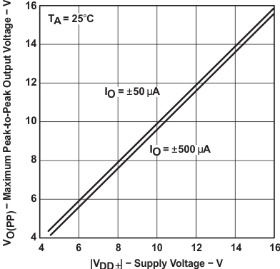
Maximum Peak-to-Peak Output Voltage vs
Supply Voltage
4 Revision History
Changes from G Revision (May 2004) to H Revision
- Added Feature Description section, Device Functional Modes, Application and Implementation section, Power Supply Recommendations section, Layout section, Device and Documentation Supportsection, and Mechanical, Packaging, and Orderable Information section.Go
- Added ESD Rating table for the D and PW package devices. Go
5 Pin Configuration and Functions
D, JG, P, or PW Package

FK Package

U Package

D, J, N, PW, or W Package

FK Package

Pin Functions
| PIN | I/O | DESCRIPTION | |||||
|---|---|---|---|---|---|---|---|
| NAME | NO. | ||||||
| TLC2272 | TLC2274 | ||||||
| D, JG, P, or PW | FK | U | D, J, N, PW, or W | FK | |||
| 1IN+ | 3 | 7 | 4 | 3 | 4 | I | Non-inverting input, Channel 1 |
| 1IN- | 2 | 5 | 3 | 2 | 3 | I | Inverting input, Channel 1 |
| 1OUT | 1 | 2 | 2 | 1 | 2 | O | Output, Channel 1 |
| 2IN+ | 5 | 12 | 6 | 5 | 8 | I | Non-inverting input, Channel 2 |
| 2IN- | 6 | 15 | 7 | 6 | 9 | I | Inverting input, Channel 2 |
| 2OUT | 7 | 17 | 8 | 7 | 10 | O | Output, Channel 2 |
| 3IN+ | — | — | — | 10 | 14 | I | Non-inverting input, Channel 3 |
| 3IN- | — | — | — | 9 | 13 | I | Inverting input, Channel 3 |
| 3OUT | — | — | — | 8 | 12 | O | Output, Channel 3 |
| 4IN+ | — | — | — | 12 | 18 | I | Non-inverting input, Channel 4 |
| 4IN- | — | — | — | 13 | 19 | I | Inverting input, Channel 4 |
| 4OUT | — | — | — | 14 | 20 | O | Output, Channel 4 |
| VDD+ | 8 | 20 | 9 | 4 | 6 | — | Positive (highest) supply |
| VDD– | — | — | — | 11 | 16 | — | Negative (lowest) supply |
| VDD–/GND | 4 | 10 | 5 | — | — | — | Negative (lowest) supply |
| NC | — | 1, 3, 4, 6, 8, 9, 11, 13, 14, 16, 18, 19 | 1, 10 | — | 1, 5, 7, 11, 15, 17 | — | No Connection |
6 Specifications
6.1 Absolute Maximum Ratings
over operating free-air temperature range (unless otherwise noted)(1)| MIN | MAX | UNIT | ||
|---|---|---|---|---|
| Supply voltage, VDD+(2) | 8 | V | ||
| VDD-(2) | –8 | V | ||
| Differential input voltage, VID(3) | ±16 | V | ||
| Input voltage, VI(any input)(2) | VDD− − 0.3 | VDD+ | V | |
| Input current, II (any input) | ±5 | mA | ||
| Output current, IO | ±50 | mA | ||
| Total current into VDD+ | ±50 | mA | ||
| Total current out of VDD– | ±50 | mA | ||
| Duration of short-circuit current at (or below) 25°C(4) | Unlimited | |||
| Operating free-air temperature range, TA | C level parts | 0 | 70 | °C |
| I, Q level parts | –40 | 125 | ||
| M level parts | –55 | 125 | ||
| Lead temperature 1,6 mm (1/16 inch) from case for 10 seconds | D, N, P or PW package | 260 | °C | |
| Lead temperature 1,6 mm (1/16 inch) from case for 60 seconds | J or U package | 300 | °C | |
| Storage temperature, Tstg | –65 | 150 | °C | |
6.2 ESD Ratings
| VALUE | UNIT | ||||
|---|---|---|---|---|---|
| V(ESD) | Electrostatic discharge | Human-body model (HBM), per AEC Q100-002(1) | Q-grade and M-grade devices in D and PW packages | ±2000 | V |
| Charged-device model (CDM), per AEC Q100-011 | Q-grade and M-grade devices in D and PW packages | ±1000 | |||
6.3 Recommended Operating Conditions
| MIN | MAX | UNIT | |||
|---|---|---|---|---|---|
| VDD± | Supply voltage | C LEVEL PARTS | ±2.2 | ±8 | V |
| I LEVEL PARTS | ±2.2 | ±8 | |||
| Q LEVEL PARTS | ±2.2 | ±8 | |||
| M LEVEL PARTS | ±2.2 | ±8 | |||
| VI | Input voltage | C LEVEL PARTS | VDD− | VDD+ −1.5 | V |
| I LEVEL PARTS | VDD− | VDD+ −1.5 | |||
| Q LEVEL PARTS | VDD− | VDD+ −1.5 | |||
| M LEVEL PARTS | VDD− | VDD+ −1.5 | |||
| VIC | Common-mode input voltage | C LEVEL PARTS | VDD− | VDD+ −1.5 | V |
| I LEVEL PARTS | VDD− | VDD+ −1.5 | |||
| Q LEVEL PARTS | VDD− | VDD+ −1.5 | |||
| M LEVEL PARTS | VDD− | VDD+ −1.5 | |||
| TA | Operating free-air temperature | C LEVEL PARTS | 0 | 70 | °C |
| I LEVEL PARTS | –40 | 125 | |||
| Q LEVEL PARTS | –40 | 125 | |||
| M LEVEL PARTS | –55 | 125 | |||
6.4 Thermal Information
| THERMAL METRIC(1) | TLC2272 | TLC2274 | UNIT | |||||||||
|---|---|---|---|---|---|---|---|---|---|---|---|---|
| D (SOIC) |
P (PDIP) |
PW (TSSOP) |
FK (LCCC) |
U (CFP) |
D (SOIC) |
N (PDIP) |
PW (TSSOP) |
FK (LCCC) |
J (CDIP) |
|||
| 8-PIN | 8-PIN | 8-PIN | 20-PIN | 10-PIN | 14-PIN | 14-PIN | 14-PIN | 20-PIN | 14-PIN | |||
| RθJA | Junction-to-ambient thermal resistance (2)(3) | 115.6 | 58.5 | 175.8 | — | — | 83.8 | — | 111.6 | — | — | °C/W |
| RθJC(top) | Junction-to-case (top) thermal resistance (2)(3) | 61.8 | 48.3 | 58.8 | 18 | 121.3 | 43.2 | 34 | 41.2 | 16 | 16.2 | °C/W |
| RθJB | Junction-to-board thermal resistance | 55.9 | 35.6 | 104.3 | — | — | 38.4 | — | 54.7 | — | — | °C/W |
| ψJT | Junction-to-top characterization parameter | 14.3 | 25.9 | 5.9 | — | — | 9.4 | — | 3.9 | — | — | °C/W |
| ψJB | Junction-to-board characterization parameter | 55.4 | 35.5 | 102.6 | — | — | 38.1 | — | 53.9 | — | — | °C/W |
| RθJC(bot) | Junction-to-case (bottom) thermal resistance | — | — | — | — | 8.68 | — | — | — | — | — | °C/W |
6.5 TLC2272 and TLC2272A Electrical Characteristics VDD = 5 V
at specified free-air temperature, VDD = 5 V; TA = 25°C, unless otherwise noted.| PARAMETER | TEST CONDITIONS | MIN | TYP | MAX | UNIT | |||
|---|---|---|---|---|---|---|---|---|
| VIO | Input offset voltage | VIC = 0 V, VDD± = ±2.5 V, VO = 0 V, RS = 50 Ω |
TLC2272 | TA = 25°C | 300 | 2500 | µV | |
| TLC2272A | 300 | 950 | ||||||
| TLC2272 | Full Range(1) | 3000 | ||||||
| TLC2272A | 1500 | |||||||
| αVIO | Temperature coefficient of input offset voltage |
VIC = 0 V, VDD± = ±2.5 V, VO = 0 V, RS = 50 Ω | 2 | μV/°C | ||||
| Input offset voltage long-term drift(3) | VIC = 0 V, VDD± = ±2.5 V, VO = 0 V, RS = 50 Ω | 0.002 | μV/mo | |||||
| IIO | Input offset current | VIC = 0 V, VDD± = ±2.5 V, VO = 0 V, RS = 50 Ω |
All level parts | TA = 25°C | 0.5 | 60 | pA | |
| C level part | TA = 0°C to 80°C | 100 | ||||||
| I level part | TA = –40°C to 85°C | 150 | ||||||
| Q level part | TA = –40°C to 125°C | 800 | ||||||
| M level part | TA = –55°C to 125°C | 800 | ||||||
| IIB | Input bias current | VIC = 0 V, VDD± = ±2.5 V, VO = 0 V, RS = 50 Ω |
All level parts | TA = 25°C | 1 | 60 | pA | |
| C level part | TA = 0°C to 80°C | 100 | ||||||
| I level part | TA = –40°C to 85°C | 150 | ||||||
| Q level part | TA = –40°C to 125°C | 800 | ||||||
| M level part | TA = –55°C to 125°C | 800 | ||||||
| VICR | Common-mode input voltage | RS = 50 Ω; |VIO | ≤ 5 mV | TA = 25°C | –0.3 | 2.5 | 4 | V | |
| Full Range(1) | 0 | 2.5 | 3.5 | |||||
| VOH | High-level output voltage | IOH = −20 μA | 4.99 | V | ||||
| IOH = −200 μA | TA = 25°C | 4.85 | 4.93 | |||||
| Full Range(1) | 4.85 | |||||||
| IOH = −1 mA | TA = 25°C | 4.25 | 4.65 | |||||
| Full Range(1) | 4.25 | |||||||
| VOL | Low-level output voltage | VIC = 2.5 V | IOL = 50 μA | 0.01 | V | |||
| IOL = 500 μA | TA = 25°C | 0.09 | 0.15 | |||||
| Full Range(1) | 0.15 | |||||||
| IOL = 5 mA | TA = 25°C | 0.9 | 1.5 | |||||
| Full Range(1) | 1.5 | |||||||
| AVD | Large-signal differential voltage amplification |
VIC = 2.5 V, VO = 1 V to 4 V; RL = 10 kΩ(2) |
C level part | TA = 25°C | 15 | 35 | V/mV | |
| TA = 0°C to 80°C | 15 | |||||||
| I level part | TA = 25°C | 15 | 35 | |||||
| TA = –40°C to 85°C | 15 | |||||||
| Q level part | TA = 25°C | 10 | 35 | |||||
| TA = –40°C to 125°C | 10 | |||||||
| M level part | TA = 25°C | 10 | 35 | |||||
| TA = –55°C to 125°C | 10 | |||||||
| VIC = 2.5 V, VO = 1 V to 4 V; RL = 1 MΩ(2) | 175 | |||||||
| rid | Differential input resistance | 1012 | Ω | |||||
| ri | Common-mode input resistance | 1012 | Ω | |||||
| ci | Common-mode input capacitance | f = 10 kHz, P package | 8 | pF | ||||
| zo | Closed-loop output impedance | f = 1 MHz, AV = 10 | 140 | Ω | ||||
| CMRR | Common-mode rejection ratio | VIC = 0 V to 2.7 V, VO = 2.5 V, RS = 50 Ω |
TA = 25°C | 70 | 75 | dB | ||
| Full Range(1) | 70 | |||||||
| kSVR | Supply-voltage rejection ratio (ΔVDD / ΔVIO) |
VDD = 4.4 V to 16 V, VIC = VDD / 2, no load |
TA = 25°C | 80 | 95 | dB | ||
| Full Range(1) | 80 | |||||||
| IDD | Supply currrent | VO = 2.5 V, no load | TA = 25°C | 2.2 | 3 | mA | ||
| Full Range(1) | 3 | |||||||
| SR | Slew rate at unity gain | VO = 0.5 V to 2.5 V, RL = 10 kΩ(2), CL = 100 pF(2) |
TA = 25°C | 2.3 | 3.6 | V/µs | ||
| Full Range(1) | 1.7 | |||||||
| Vn | Equivalent input noise voltage | f = 10 Hz | 50 | nV/√Hz | ||||
| f = 1 kHz | 9 | |||||||
| VNPP | Peak-to-peak equivalent input noise voltage |
f = 0.1 Hz to 1 Hz | 1 | µV | ||||
| f = 0.1 Hz to 10 Hz | 1.4 | |||||||
| In | Equivalent input noise current | 0.6 | fA/√Hz | |||||
| THD+N | Total harmonic distortion + noise | VO = 0.5 V to 2.5 V, f = 20 kHz, RL = 10 kΩ(2) |
AV = 1 | 0.0013% | ||||
| AV = 10 | 0.004% | |||||||
| AV = 100 | 0.03% | |||||||
| Gain-bandwidth product | f = 10 kHz, RL = 10 kΩ(2), CL = 100 pF(2) | 2.18 | MHz | |||||
| BOM | Maximum output-swing bandwidth | VO(PP) = 2 V, AV = 1, RL = 10 kΩ(2), CL = 100 pF(2) | 1 | MHz | ||||
| ts | Settling time | AV = –1, RL = 10 kΩ(2), Step = 0.5 V to 2.5 V, CL = 100 pF(2) |
To 0.1% | 1.5 | µs | |||
| To 0.01% | 2.6 | |||||||
| φm | Phase margin at unity gain | RL = 10 kΩ(2), CL = 100 pF(2) | 50° | |||||
| Gain margin | RL = 10 kΩ(2), CL = 100 pF(2) | 10 | dB | |||||
6.6 TLC2272 and TLC2272A Electrical Characteristics VDD± = ±5 V
at specified free-air temperature, VDD± = ±5 V; TA = 25°C, unless otherwise noted.| PARAMETER | TEST CONDITIONS | MIN | TYP | MAX | UNIT | |||
|---|---|---|---|---|---|---|---|---|
| VIO | Input offset voltage | VIC = 0 V, VO = 0 V, RS = 50 Ω |
TLC2272 | TA = 25°C | 300 | 2500 | µV | |
| TLC2272A | 300 | 950 | ||||||
| TLC2272 | Full Range(1) | 3000 | ||||||
| TLC2272A | 1500 | |||||||
| αVIO | Temperature coefficient of input offset voltage |
VIC = 0 V, VO = 0 V, RS = 50 Ω | 2 | μV/°C | ||||
| Input offset voltage long-term drift(3) | VIC = 0 V, VO = 0 V, RS = 50 Ω | 0.002 | μV/mo | |||||
| IIO | Input offset current | VIC = 0 V, VO = 0 V, RS = 50 Ω |
All level parts | TA = 25°C | 0.5 | 60 | pA | |
| C level part | TA = 0°C to 80°C | 100 | ||||||
| I level part | TA = –40°C to 85°C | 150 | ||||||
| Q level part | TA = –40°C to 125°C | 800 | ||||||
| M level part | TA = –55°C to 125°C | 800 | ||||||
| IIB | Input bias current | VIC = 0 V, VO = 0 V, RS = 50 Ω |
All level parts | TA = 25°C | 1 | 60 | pA | |
| C level part | TA = 0°C to 80°C | 100 | ||||||
| I level part | TA = –40°C to 85°C | 150 | ||||||
| Q level part | TA = –40°C to 125°C | 800 | ||||||
| M level part | TA = –55°C to 125°C | 800 | ||||||
| VICR | Common-mode input voltage | RS = 50 Ω; |VIO | ≤ 5 mV | TA = 25°C | –5.3 | 0 | 4 | V | |
| Full Range(1) | –5 | 0 | 3.5 | |||||
| VOM+ | Maximum positive peak output voltage |
IO = −20 μA | 4.99 | V | ||||
| IO = −200 μA | TA = 25°C | 4.85 | 4.93 | |||||
| Full Range(1) | 4.85 | |||||||
| IO = −1 mA | TA = 25°C | 4.25 | 4.65 | |||||
| Full Range(1) | 4.25 | |||||||
| VOM- | Maximum negative peak output voltage |
VIC = 0 V, | IO = 50 μA | –4.99 | V | |||
| IO = 500 μA | TA = 25°C | –4.85 | –4.91 | |||||
| Full Range(1) | –4.85 | |||||||
| IO = 5 mA | TA = 25°C | –3.5 | –4.1 | |||||
| Full Range(1) | –3.5 | |||||||
| AVD | Large-signal differential voltage amplification |
VO = ±4 V; RL = 10 kΩ | C level part | TA = 25°C | 25 | 50 | V/mV | |
| TA = 0°C to 80°C | 25 | |||||||
| I level part | TA = 25°C | 25 | 50 | |||||
| TA = –40°C to 85°C | 25 | |||||||
| Q level part | TA = 25°C | 20 | 50 | |||||
| TA = –40°C to 125°C | 20 | |||||||
| M level part | TA = 25°C | 20 | 50 | |||||
| TA = –55°C to 125°C | 20 | |||||||
| VO = ±4 V; RL = 1 MΩ | 300 | |||||||
| rid | Differential input resistance | 1012 | Ω | |||||
| ri | Common-mode input resistance | 1012 | Ω | |||||
| ci | Common-mode input capacitance | f = 10 kHz, P package | 8 | pF | ||||
| zo | Closed-loop output impedance | f = 1 MHz, AV = 10 | 130 | Ω | ||||
| CMRR | Common-mode rejection ratio | VIC = –5 V to 2.7 V, VO = 0 V, RS = 50 Ω |
TA = 25°C | 75 | 80 | dB | ||
| Full Range(1) | 75 | |||||||
| kSVR | Supply-voltage rejection ratio (ΔVDD / ΔVIO) |
VDD+ = 2.2 V to ±8 V, VIC = 0 V, no load |
TA = 25°C | 80 | 95 | dB | ||
| Full Range(1) | 80 | |||||||
| IDD | Supply currrent | VO = 0 V, no load | TA = 25°C | 2.4 | 3 | mA | ||
| Full Range(1) | 3 | |||||||
| SR | Slew rate at unity gain | VO = ±2.3 V, RL = 10 kΩ, CL = 100 pF |
TA = 25°C | 2.3 | 3.6 | V/µs | ||
| Full Range(1) | 1.7 | |||||||
| Vn | Equivalent input noise voltage | f = 10 Hz | 50 | nV/√Hz | ||||
| f = 1 kHz | 9 | |||||||
| VNPP | Peak-to-peak equivalent input noise voltage |
f = 0.1 Hz to 1 Hz | 1 | µV | ||||
| f = 0.1 Hz to 10 Hz | 1.4 | |||||||
| In | Equivalent input noise current | 0.6 | fA/√Hz | |||||
| THD+N | Total harmonic distortion + noise | VO = ±2.3, f = 20 kHz, RL = 10 kΩ |
AV = 1 | 0.0011% | ||||
| AV = 10 | 0.004% | |||||||
| AV = 100 | 0.03% | |||||||
| Gain-bandwidth product | f = 10 kHz, RL = 10 kΩ, CL = 100 pF | 2.25 | MHz | |||||
| BOM | Maximum output-swing bandwidth | VO(PP) = 4.6 V, AV = 1, RL = 10 kΩ, CL = 100 pF | 0.54 | MHz | ||||
| ts | Settling time | AV = –1, RL = 10 kΩ, Step = –2.3 V to 2.3 V, CL = 100 pF |
To 0.1% | 1.5 | µs | |||
| To 0.01% | 3.2 | |||||||
| φm | Phase margin at unity gain | RL = 10 kΩ, CL = 100 pF | 52° | |||||
| Gain margin | RL = 10 kΩ, CL = 100 pF | 10 | dB | |||||
6.7 TLC2274 and TLC2274A Electrical Characteristics VDD = 5 V
at specified free-air temperature, VDD = 5 V; TA = 25°C, unless otherwise noted.| PARAMETER | TEST CONDITIONS | MIN | TYP | MAX | UNIT | |||
|---|---|---|---|---|---|---|---|---|
| VIO | Input offset voltage | VIC = 0 V, VDD± = ±2.5 V, VO = 0 V, RS = 50 Ω |
TLC2274 | TA = 25°C | 300 | 2500 | µV | |
| TLC2274A | 300 | 950 | ||||||
| TLC2274 | Full Range(1) | 3000 | ||||||
| TLC2274A | 1500 | |||||||
| αVIO | Temperature coefficient of input offset voltage |
VIC = 0 V, VDD± = ±2.5 V, VO = 0 V, RS = 50 Ω | 2 | μV/°C | ||||
| Input offset voltage long-term drift(3) | VIC = 0 V, VDD± = ±2.5 V, VO = 0 V, RS = 50 Ω | 0.002 | μV/mo | |||||
| IIO | Input offset current | VIC = 0 V, VDD± = ±2.5 V, VO = 0 V, RS = 50 Ω |
All level parts | TA = 25°C | 0.5 | 60 | pA | |
| C level part | TA = 0°C to 80°C | 100 | ||||||
| I level part | TA = –40°C to 85°C | 150 | ||||||
| Q level part | TA = –40°C to 125°C | 800 | ||||||
| M level part | TA = –55°C to 125°C | 800 | ||||||
| IIB | Input bias current | VIC = 0 V, VDD± = ±2.5 V, VO = 0 V, RS = 50 Ω |
All level parts | TA = 25°C | 1 | 60 | pA | |
| C level part | TA = 0°C to 80°C | 100 | ||||||
| I level part | TA = –40°C to 85°C | 150 | ||||||
| Q level part | TA = –40°C to 125°C | 800 | ||||||
| M level part | TA = –55°C to 125°C | 800 | ||||||
| VICR | Common-mode input voltage | RS = 50 Ω; |VIO | ≤ 5 mV | TA = 25°C | –0.3 | 2.5 | 4 | V | |
| Full Range(1) | 0 | 2.5 | 3.5 | |||||
| VOH | High-level output voltage | IOH = −20 μA | 4.99 | V | ||||
| IOH = −200 μA | TA = 25°C | 4.85 | 4.93 | |||||
| Full Range(1) | 4.85 | |||||||
| IOH = −1 mA | TA = 25°C | 4.25 | 4.65 | |||||
| Full Range(1) | 4.25 | |||||||
| VOL | Low-level output voltage | VIC = 2.5 V | IOL = 50 μA | 0.01 | V | |||
| IOL = 500 μA | TA = 25°C | 0.09 | 0.15 | |||||
| Full Range(1) | 0.15 | |||||||
| IOL = 5 mA | TA = 25°C | 0.9 | 1.5 | |||||
| Full Range(1) | 1.5 | |||||||
| AVD | Large-signal differential voltage amplification |
VIC = 2.5 V, VO = 1 V to 4 V; RL = 10 kΩ(2) |
C level part | TA = 25°C | 15 | 35 | V/mV | |
| TA = 0°C to 80°C | 15 | |||||||
| I level part | TA = 25°C | 15 | 35 | |||||
| TA = –40°C to 85°C | 15 | |||||||
| Q level part | TA = 25°C | 10 | 35 | |||||
| TA = –40°C to 125°C | 10 | |||||||
| M level part | TA = 25°C | 10 | 35 | |||||
| TA = –55°C to 125°C | 10 | |||||||
| VIC = 2.5 V, VO = 1 V to 4 V; RL = 1 MΩ(2) | 175 | |||||||
| rid | Differential input resistance | 1012 | Ω | |||||
| ri | Common-mode input resistance | 1012 | Ω | |||||
| ci | Common-mode input capacitance | f = 10 kHz, P package | 8 | pF | ||||
| zo | Closed-loop output impedance | f = 1 MHz, AV = 10 | 140 | Ω | ||||
| CMRR | Common-mode rejection ratio | VIC = 0 V to 2.7 V, VO = 2.5 V, RS = 50 Ω |
TA = 25°C | 70 | 75 | dB | ||
| Full Range(1) | 70 | |||||||
| kSVR | Supply-voltage rejection ratio (ΔVDD / ΔVIO) |
VDD = 4.4 V to 16 V, VIC = VDD / 2, no load |
TA = 25°C | 80 | 95 | dB | ||
| Full Range(1) | 80 | |||||||
| IDD | Supply currrent | VO = 2.5 V, no load | TA = 25°C | 4.4 | 6 | mA | ||
| Full Range(1) | 6 | |||||||
| SR | Slew rate at unity gain | VO = 0.5 V to 2.5 V, RL = 10 kΩ(2), CL = 100 pF(2) |
TA = 25°C | 2.3 | 3.6 | V/µs | ||
| Full Range(1) | 1.7 | |||||||
| Vn | Equivalent input noise voltage | f = 10 Hz | 50 | nV/√Hz | ||||
| f = 1 kHz | 9 | |||||||
| VNPP | Peak-to-peak equivalent input noise voltage |
f = 0.1 Hz to 1 Hz | 1 | µV | ||||
| f = 0.1 Hz to 10 Hz | 1.4 | |||||||
| In | Equivalent input noise current | 0.6 | fA/√Hz | |||||
| THD+N | Total harmonic distortion + noise | VO = 0.5 V to 2.5 V, f = 20 kHz, RL = 10 kΩ(2) |
AV = 1 | 0.0013% | ||||
| AV = 10 | 0.004% | |||||||
| AV = 100 | 0.03% | |||||||
| Gain-bandwidth product | f = 10 kHz, RL = 10 kΩ(2), CL = 100 pF(2) | 2.18 | MHz | |||||
| BOM | Maximum output-swing bandwidth | VO(PP) = 2 V, AV = 1, RL = 10 kΩ(2), CL = 100 pF(2) | 1 | MHz | ||||
| ts | Settling time | AV = –1, RL = 10 kΩ(2), Step = 0.5 V to 2.5 V, CL = 100 pF(2) |
To 0.1% | 1.5 | µs | |||
| To 0.01% | 2.6 | |||||||
| φm | Phase margin at unity gain | RL = 10 kΩ(2), CL = 100 pF(2) | 50° | |||||
| Gain margin | RL = 10 kΩ(2), CL = 100 pF(2) | 10 | dB | |||||
6.8 TLC2274 and TLC2274A Electrical Characteristics VDD± = ±5 V
at specified free-air temperature, VDD± = ±5 V; TA = 25°C, unless otherwise noted.| PARAMETER | TEST CONDITIONS | MIN | TYP | MAX | UNIT | |||
|---|---|---|---|---|---|---|---|---|
| VIO | Input offset voltage | VIC = 0 V, VO = 0 V, RS = 50 Ω |
TLC2274 | TA = 25°C | 300 | 2500 | µV | |
| TLC2274A | 300 | 950 | ||||||
| TLC2274 | Full Range(1) | 3000 | ||||||
| TLC2274A | 1500 | |||||||
| αVIO | Temperature coefficient of input offset voltage |
VIC = 0 V, VO = 0 V, RS = 50 Ω | 2 | μV/°C | ||||
| Input offset voltage long-term drift(3) | VIC = 0 V, VO = 0 V, RS = 50 Ω | 0.002 | μV/mo | |||||
| IIO | Input offset current | VIC = 0 V, VO = 0 V, RS = 50 Ω |
All level parts | TA = 25°C | 0.5 | 60 | pA | |
| C level part | TA = 0°C to 80°C | 100 | ||||||
| I level part | TA = –40°C to 85°C | 150 | ||||||
| Q level part | TA = –40°C to 125°C | 800 | ||||||
| M level part | TA = –55°C to 125°C | 800 | ||||||
| IIB | Input bias current | VIC = 0 V, VO = 0 V, RS = 50 Ω |
All level parts | TA = 25°C | 1 | 60 | pA | |
| C level part | TA = 0°C to 80°C | 100 | ||||||
| I level part | TA = –40°C to 85°C | 150 | ||||||
| Q level part | TA = –40°C to 125°C | 800 | ||||||
| M level part | TA = –55°C to 125°C | 800 | ||||||
| VICR | Common-mode input voltage | RS = 50 Ω; |VIO | ≤ 5 mV | TA = 25°C | –5.3 | 0 | 4 | V | |
| Full Range(1) | –5 | 0 | 3.5 | |||||
| VOM+ | Maximum positive peak output voltage |
IO = −20 μA | 4.99 | V | ||||
| IO = −200 μA | TA = 25°C | 4.85 | 4.93 | |||||
| Full Range(1) | 4.85 | |||||||
| IO = −1 mA | TA = 25°C | 4.25 | 4.65 | |||||
| Full Range(1) | 4.25 | |||||||
| VOM- | Maximum negative peak output voltage |
VIC = 0 V | IO = 50 μA | –4.99 | V | |||
| IO = 500 μA | TA = 25°C | –4.85 | –4.91 | |||||
| Full Range(1) | –4.85 | |||||||
| IO = 5 mA | TA = 25°C | –3.5 | –4.1 | |||||
| Full Range(1) | –3.5 | |||||||
| AVD | Large-signal differential voltage amplification |
VO = ±4 V; RL = 10 kΩ | C level part | TA = 25°C | 25 | 50 | V/mV | |
| TA = 0°C to 80°C | 25 | |||||||
| I level part | TA = 25°C | 25 | 50 | |||||
| TA = –40°C to 85°C | 25 | |||||||
| Q level part | TA = 25°C | 20 | 50 | |||||
| TA = –40°C to 125°C | 20 | |||||||
| M level part | TA = 25°C | 20 | 50 | |||||
| TA = –55°C to 125°C | 20 | |||||||
| VO = ±4 V; RL = 1 MΩ | 300 | |||||||
| rid | Differential input resistance | 1012 | Ω | |||||
| ri | Common-mode input resistance | 1012 | Ω | |||||
| ci | Common-mode input capacitance | f = 10 kHz, P package | 8 | pF | ||||
| zo | Closed-loop output impedance | f = 1 MHz, AV = 10 | 130 | Ω | ||||
| CMRR | Common-mode rejection ratio | VIC = –5 V to 2.7 V, VO = 0 V, RS = 50 Ω |
TA = 25°C | 75 | 80 | dB | ||
| Full Range(1) | 75 | |||||||
| kSVR | Supply-voltage rejection ratio (ΔVDD / ΔVIO) |
VDD+ = 2.2 V to ±8 V, VIC = 0 V, no load |
TA = 25°C | 80 | 95 | dB | ||
| Full Range(1) | 80 | |||||||
| IDD | Supply currrent | VO = 0 V, no load | TA = 25°C | 4.8 | 6 | mA | ||
| Full Range(1) | 6 | |||||||
| SR | Slew rate at unity gain | VO = ±2.3 V, RL = 10 kΩ, CL = 100 pF |
TA = 25°C | 2.3 | 3.6 | V/µs | ||
| Full Range(1) | 1.7 | |||||||
| Vn | Equivalent input noise voltage | f = 10 Hz | 50 | nV/√Hz | ||||
| f = 1 kHz | 9 | |||||||
| VNPP | Peak-to-peak equivalent input noise voltage |
f = 0.1 Hz to 1 Hz | 1 | µV | ||||
| f = 0.1 Hz to 10 Hz | 1.4 | |||||||
| In | Equivalent input noise current | 0.6 | fA/√Hz | |||||
| THD+N | Total harmonic distortion + noise | VO = ±2.3, f = 20 kHz, RL = 10 kΩ |
AV = 1 | 0.0011% | ||||
| AV = 10 | 0.004% | |||||||
| AV = 100 | 0.03% | |||||||
| Gain-bandwidth product | f = 10 kHz, RL = 10 kΩ, CL = 100 pF | 2.25 | MHz | |||||
| BOM | Maximum output-swing bandwidth | VO(PP) = 4.6 V, AV = 1, RL = 10 kΩ, CL = 100 pF | 0.54 | MHz | ||||
| ts | Settling time | AV = –1, RL = 10 kΩ, Step = –2.3 V to 2.3 V, CL = 100 pF |
To 0.1% | 1.5 | µs | |||
| To 0.01% | 3.2 | |||||||
| φm | Phase margin at unity gain | RL = 10 kΩ, CL = 100 pF | 52° | |||||
| Gain margin | RL = 10 kΩ, CL = 100 pF | 10 | dB | |||||
6.9 Typical Characteristics
Table 1. Table of Graphs
| FIGURE(1) | |||
|---|---|---|---|
| VIO | Input offset voltage | Distribution | 1, 2, 3, 4 |
| vs Common-mode voltage | 5, 6 | ||
| αVIO | Input offset voltage temperature coefficient | Distribution | 7, 8, 9, 10(2) |
| IIB /IIO | Input bias and input offset current | vs Free-air temperature | 11(2) |
| VI | Input voltage | vs Supply voltage | 12 |
| vs Free-air temperature | 13(2) | ||
| VOH | High-level output voltage | vs High-level output current | 14(2) |
| VOL | Low-level output voltage | vs Low-level output current | 15, 16(2) |
| VOM+ | Maximum positive peak output voltage | vs Output current | 17(2) |
| VOM- | Maximum negative peak output voltage | vs Output current | 18(2) |
| VO(PP) | Maximum peak-to-peak output voltage | vs Frequency | 19 |
| IOS | Short-circuit output current | vs Supply voltage | 20 |
| vs Free-air temperature | 21(2) | ||
| VO | Output voltage | vs Differential input voltage | 22, 23 |
| AVD | Large-signal differential voltage amplification | vs Load resistance | 24 |
| Large-signal differential voltage amplification and phase margin | vs Frequency | 25, 26 | |
| Large-signal differential voltage amplification | vs Free-air temperature | 27(2), 28(2) | |
| z0 | Output impedance | vs Frequency | 29, 30 |
| CMRR | Common-mode rejection ratio | vs Frequency | 31 |
| vs Free-air temperature | 32 | ||
| kSVR | Supply-voltage rejection ratio | vs Frequency | 33, 34 |
| vs Free-air temperature | 35(2) | ||
| IDD | Supply current | vs Supply voltage | 36(2), 37(2) |
| vs Free-air temperature | 38(2), 39(2) | ||
| SR | Slew rate | vs Load Capacitance | 40 |
| vs Free-air temperature | 41(2) | ||
| VO | Inverting large-signal pulse response | 42, 43 | |
| Voltage-follower large-signal pulse response | 44, 45 | ||
| Inverting small-signal pulse response | 46, 47 | ||
| Voltage-follower small-signal pulse response | 48, 49 | ||
| Vn | Equivalent input noise voltage | vs Frequency | 50, 51 |
| Noise voltage over a 10-second period | 52 | ||
| Integrated noise voltage | vs Frequency | 53 | |
| THD+N | Total harmonic distortion + noise | vs Frequency | 54 |
| Gain-bandwidth product | vs Supply voltage | 55 | |
| vs Free-air temperature | 56(2) | ||
| φm | Phase margin | vs Load capacitance | 57 |
| Gain margin | vs Load capacitance | 58 | |
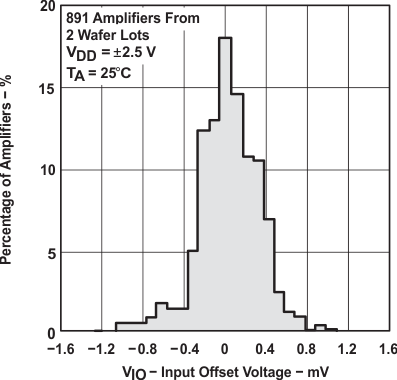 Figure 1. Distribution of TLC2272 Input Offset Voltage
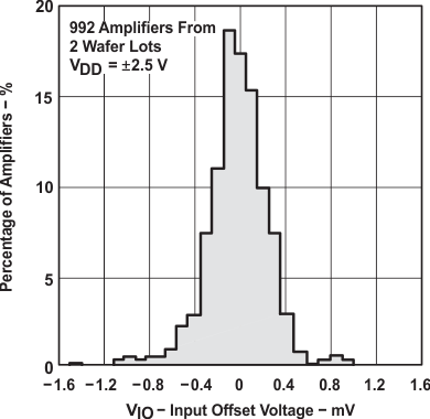 Figure 3. Distribution of TLC2274 Input Offset Voltage
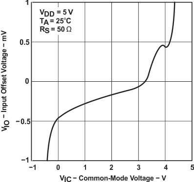 Figure 5. Input Offset Voltage vs Common-Mode Voltage
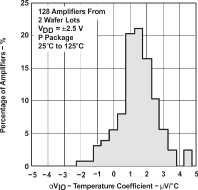 Figure 7. Distribution of TLC2272 vs
 Input Offset Voltage Temperature Coefficient
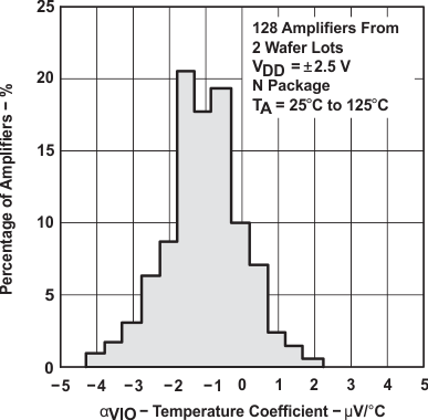 Figure 9. Distribution of TLC2274 vs
 Input Offset Voltage Temperature Coefficient
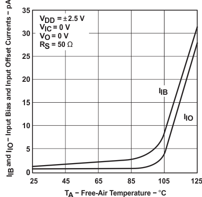 Figure 11. Input Bias and Input Offset Current vs
 Free-Air Temperature
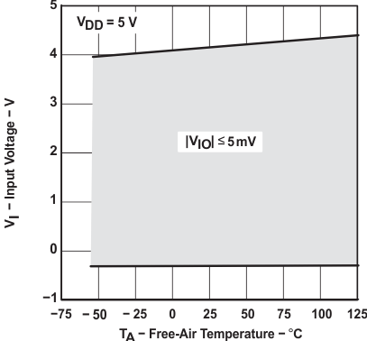 Figure 13. Input Voltage vs Free-Air Temperature
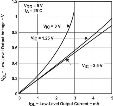 Figure 15. Low-Level Output Voltage vs
 Low-Level Output Current
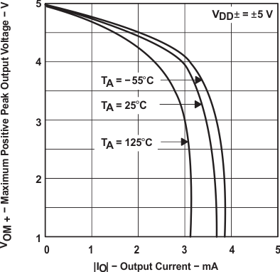 Figure 17. Maximum Positive Peak Output Voltage vs
 Output Current
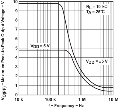 Figure 19. Maximum Peak-to-Peak Output Voltage vs
 Frequency
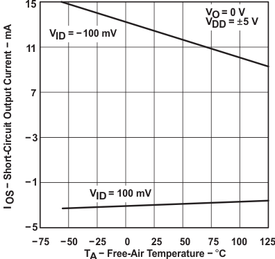 Figure 21. Short-Circuit Output Current vs
 Free-Air Temperature
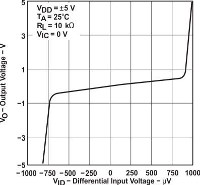 Figure 23. Output Voltage vs Differential Input Voltage
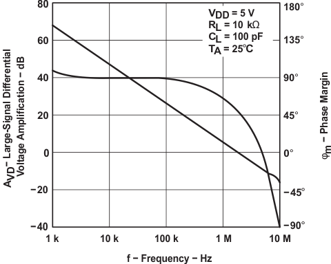 Figure 25. Large-Signal Differential Voltage Amplification and Phase Margin vs Frequency
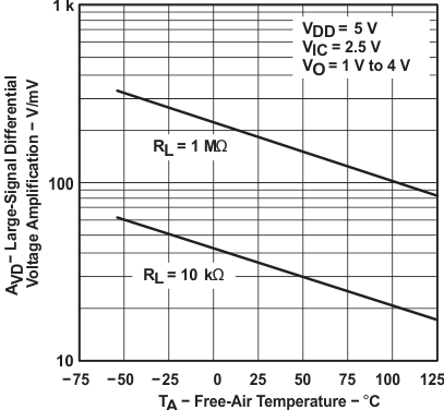 Figure 27. Large-Signal Differential Voltage Amplification vs Free-Air Temperature
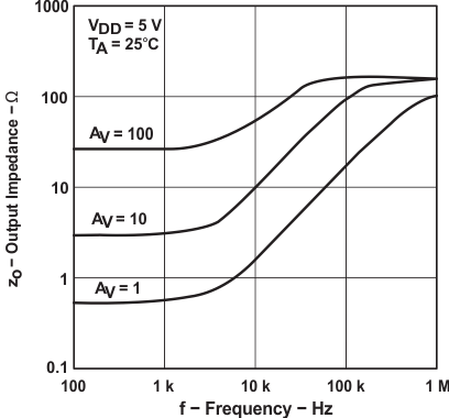 Figure 29. Output Impedance vs Frequency
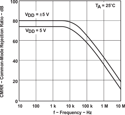 Figure 31. Common-Mode Rejection Ratio vs Frequency
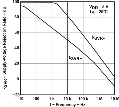 Figure 33. Supply-Voltage Rejection Ratio vs Frequency
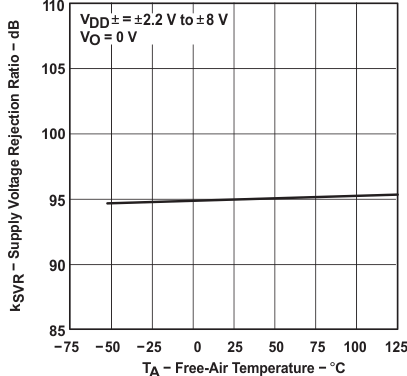 Figure 35. Supply-Voltage Rejection Ratio vs
 Free-Air Temperature
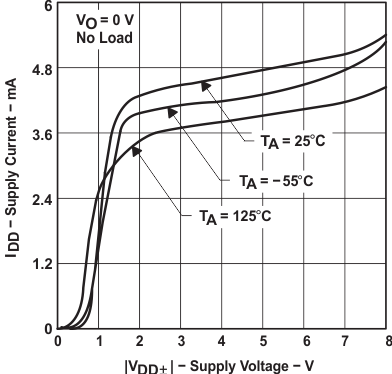 Figure 37. TLC2274 Supply Current vs Supply Voltage
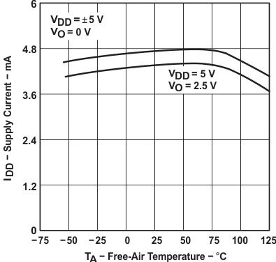 Figure 39. TLC2274 Supply Current vs Free-Air Temperature
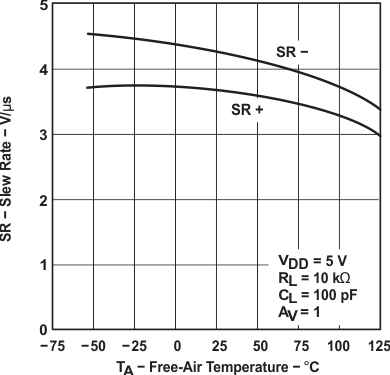 Figure 41. Slew Rate vs Free-Air Temperature
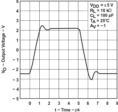 Figure 43. Inverting Large-Signal Pulse Response
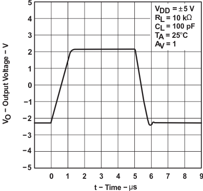 Figure 45. Voltage-Follower Large-Signal Pulse Response
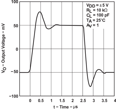 Figure 47. Inverting Small-Signal Pulse Response
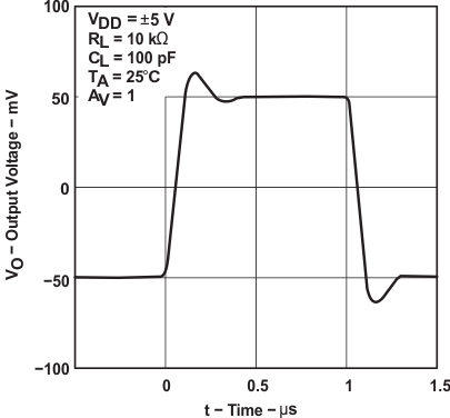 Figure 49. Voltage-Follower Small-Signal Pulse Response
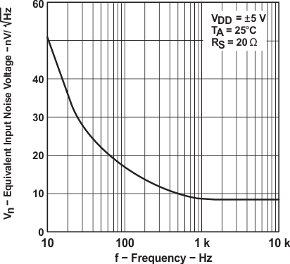 Figure 51. Equivalent Input Noise Voltage vs Frequency
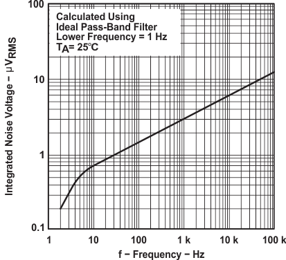 Figure 53. Integrated Noise Voltage vs Frequency
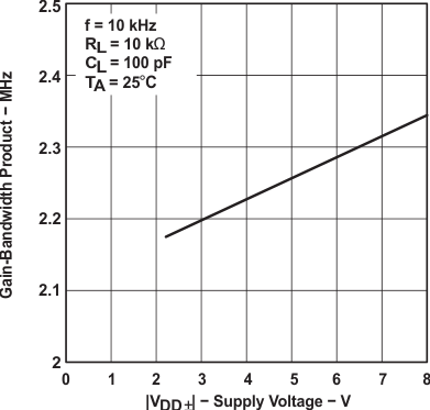 Figure 55. Gain-Bandwidth Product vs Supply Voltage
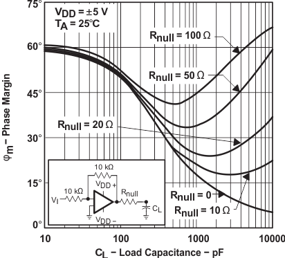 Figure 57. Phase Margin vs Load Capacitance
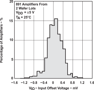 Figure 2. Distribution of TLC2272 Input Offset Voltage
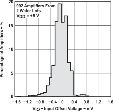 Figure 4. Distribution of TLC2274 Input Offset Voltage
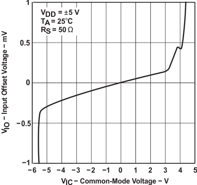 Figure 6. Input Offset Voltage vs Common-Mode Voltage
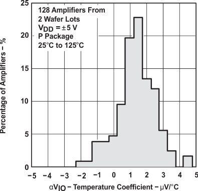 Figure 8. Distribution of TLC2272 vs
 Input Offset Voltage Temperature Coefficient
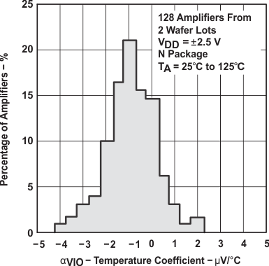 Figure 10. Distribution of TLC2274 vs
 Input Offset Voltage Temperature Coefficient
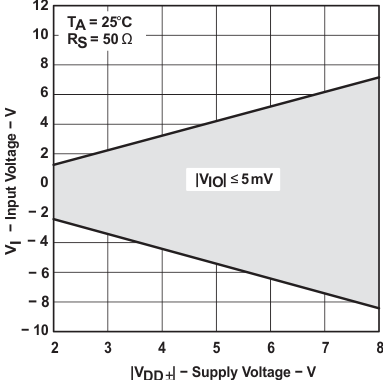 Figure 12. Input Voltage vs Supply Voltage
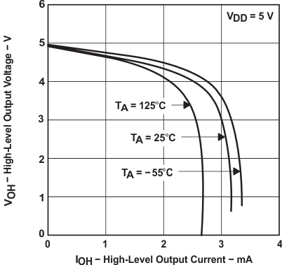 Figure 14. High-Level Output Voltage vs
 High-Level Output Current
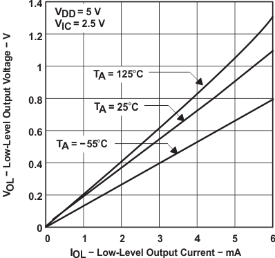 Figure 16. Low-Level Output Voltage vs
 Low-Level Output Current
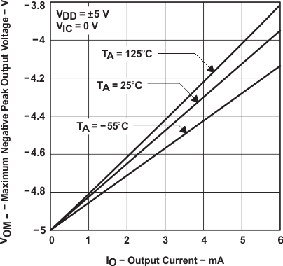 Figure 18. Maximum Positive Peak Output Voltage vs
 Output Current
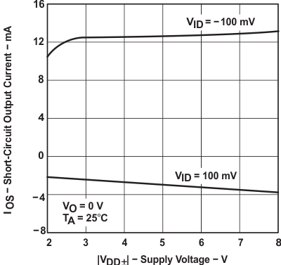 Figure 20. Short-Circuit Output Current vs Supply Voltage
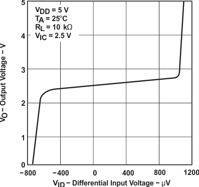 Figure 22. Output Voltage vs Differential Input Voltage
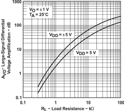 Figure 24. Large-Signal Differential Voltage Amplification vs
 Load Resistance
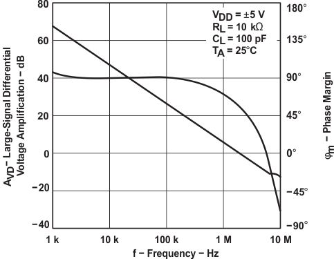 Figure 26. Large-Signal Differential Voltage Amplification and Phase Margin vs Frequency
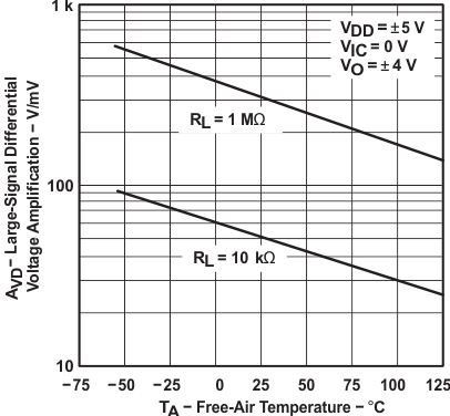 Figure 28. Large-Signal Differential Voltage Amplification vs Free-Air Temperature
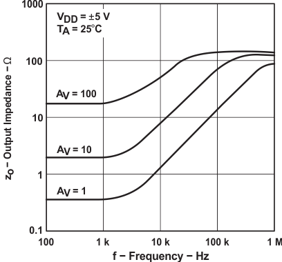 Figure 30. Output Impedance vs Frequency
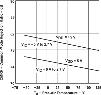 Figure 32. Common-Mode Rejection Ratio vs
 Free-Air Temperature
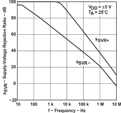 Figure 34. Supply-Voltage Rejection Ratio vs Frequency
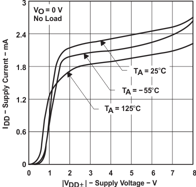 Figure 36. TLC2272 Supply Current vs Supply Voltage
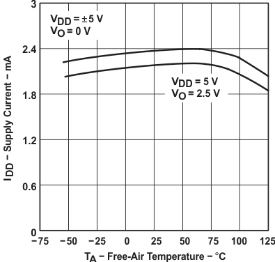 Figure 38. TLC2272 Supply Current vs Free-Air Temperature
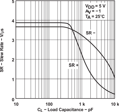 Figure 40. Slew Rate vs Load Capacitance
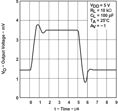 Figure 42. Inverting Large-Signal Pulse Response
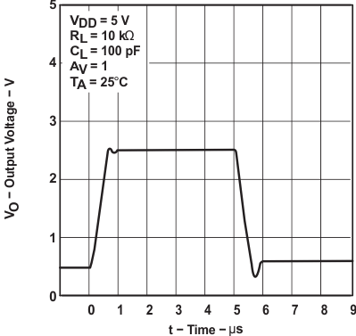 Figure 44. Voltage-Follower Large-Signal Pulse Response
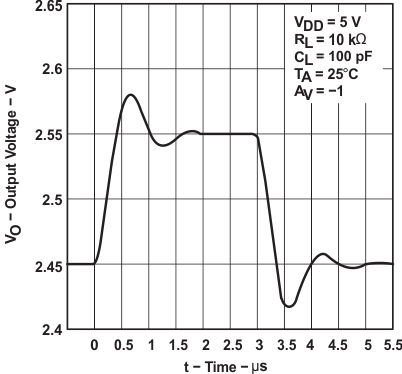 Figure 46. Inverting Small-Signal Pulse Response
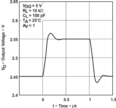 Figure 48. Voltage-Follower Small-Signal Pulse Response
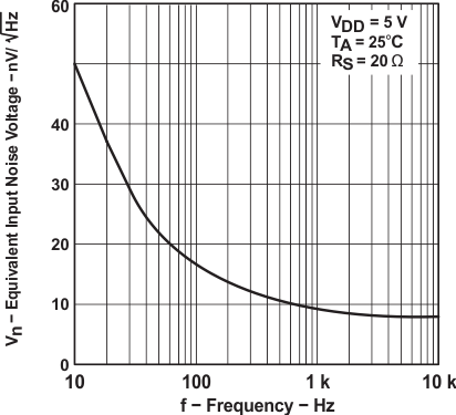 Figure 50. Equivalent Input Noise Voltage vs Frequency
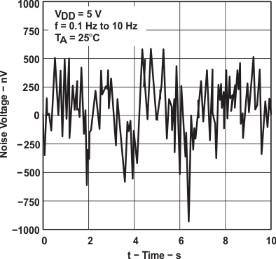 Figure 52. Noise Voltage Over a 10 Second Period
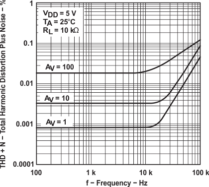 Figure 54. Total Harmonic Distortion + Noise vs Frequency
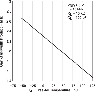 Figure 56. Gain-Bandwidth Product vs Free-Air Temperature
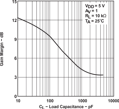 Figure 58. Gain Margin vs Load Capacitance
7 Detailed Description
7.1 Overview
The TLC227x and TLC227xA families of devices are rail-to-rail output operational amplifiers. These devices operate from 4.4-V to 16-V single supply and ±2.2-V ±8-V dual supply, are unity-gain stable, and are suitable for a wide range of general-purpose applications.
7.2 Functional Block Diagram

Table 2. Device Component Count(1)
| Component | TLC2272 | TLC2274 |
|---|---|---|
| Transistors | 38 | 76 |
| Resistors | 26 | 52 |
| Diodes | 9 | 18 |
| Capacitors | 3 | 6 |
7.3 Feature Description
The TLC227x and TLC227xA family of devices feature 2-MHz bandwidth and voltage noise of 9 nV/√Hz with performance rated from 4.4 V to 16 V across an automotive temperature range (–40°C to 125°C). LinMOS suits a wide range of audio, automotive, industrial, and instrumentation applications.
7.4 Device Functional Modes
The TLC227x and TLC227xA families of devices is powered on when the supply is connected. The devices may operate with single or dual supply, depending on the application. The devices are in its full performance once the supply is above the recommended value.
8 Application and Implementation
NOTE
Information in the following applications sections is not part of the TI component specification, and TI does not warrant its accuracy or completeness. TI’s customers are responsible for determining suitability of components for their purposes. Customers should validate and test their design implementation to confirm system functionality.
8.1 Application Information
8.1.1 Macromodel Information
Macromodel information provided was derived using MicroSim Parts™, the model generation software used with MicroSim PSpice™. The Boyle macromodel (1) and subcircuit in Figure 59 were generated using the TLC227x typical electrical and operating characteristics at TA = 25°C. Using this information, output simulations of the following key parameters can be generated to a tolerance of 20% (in most cases):
- Maximum positive output voltage swing
- Maximum negative output voltage swing
- Slew rate
- Quiescent power dissipation
- Input bias current
- Open-loop voltage amplification
- Unity gain frequency
- Common-mode rejection ratio
- Phase margin
- DC output resistance
- AC output resistance
- Short-circuit output current limit
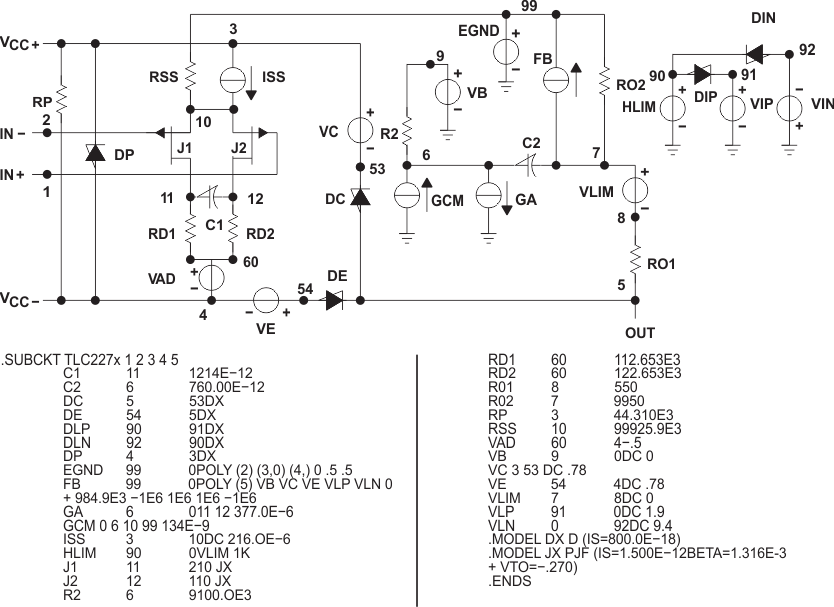 Figure 59. Boyle Macromodel and Subcircuit
8.2 Typical Application
8.2.1 High-Side Current Monitor
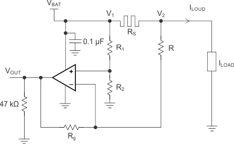 Figure 60. Equivalent Schematic (Each Amplifier)
8.2.1.1 Design Requirements
For this design example, use the parameters listed in Table 3 as the input parameters.
Table 3. Design Parameters
| PARAMETER | VALUE | |
|---|---|---|
| VBAT | Battery Voltage | 12 V |
| RSENSE | Sense Resistor | 0.1 Ω |
| ILOAD | Load Current | 0 A to 10 A |
| Operational Amplifier | Set in Differential configuration with Gain = 10 | |
8.2.1.2 Detailed Design Procedure
This circuit is designed for measuring the high-side current in automotive body control modules with 12-V battery or similar applications. The operational amplifier is set as differential with an external resistor network.
8.2.1.2.1 Differential Amplifier Equations
Equation 1 and Equation 2 are used to calculate VOUT.


In an ideal case R1 = R and R2 = Rg, and VOUT can then be calculated using Equation 3:

However, as the resistors have tolerances, they cannot be perfectly matched.
R1 = R ± ΔR1
R2 = R2 ± ΔR2
R = R ± ΔR
Rg = Rg ± ΔRg

By developing the equations and neglecting the second order, the worst case is when the tolerances add up. This is shown by Equation 5.

where
- Tol = 0.01 for 1%
- Tol = 0.001 for 0.1%
If the resistors are perfectly matched, then Tol = 0 and VOUT is calculated using Equation 6.

The highest error is from the Common mode, as shown in Equation 7.

Gain of 10, Rg / R = 10, and Tol = 1%:
Common mode error = ((4 × 0.01) / 1.1) × 12 V = 0.436 V
Gain of 10 and Tol = 0.1%:
Common mode error = 43.6 mV
The resistors were chosen from 2% batches.
R1 and R 12 kΩ
R2 and Rg 120 kΩ
Ideal Gain = 120 / 12 = 10
The measured value of the resistors:
R1 = 11.835 kΩ
R = 11.85 kΩ
R2 = 117.92 kΩ
Rg = 118.07 kΩ
8.2.1.3 Application Curves
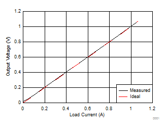 Figure 61. Output Voltage Measured vs Ideal
(0 to 1 A)
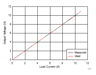 Figure 62. Output Voltage Measured vs Ideal
(0 to 10 A)