-
TPS53515 1.5-V to 18-V (4.5-V to 25-V Bias) Input, 12-A Single Synchronous Step-Down SWIFT™ Converter
- 1 Features
- 2 Applications
- 3 Description
- 4 Revision History
- 5 Pin Configuration and Functions
- 6 Specifications
-
7 Detailed Description
- 7.1 Overview
- 7.2 Functional Block Diagram
- 7.3
Feature Description
- 7.3.1 5-V LDO and VREG Start-Up
- 7.3.2 Enable, Soft Start, and Mode Selection
- 7.3.3 Frequency Selection
- 7.3.4 D-CAP3 Control and Mode Selection
- 7.3.5 Power-Good
- 7.3.6 Current Sense and Overcurrent Protection
- 7.3.7 Overvoltage and Undervoltage Protection
- 7.3.8 Out-of-Bounds Operation
- 7.3.9 UVLO Protection
- 7.3.10 Thermal Shutdown
- 7.4 Device Functional Modes
- 8 Application and Implementation
- 9 Power Supply Recommendations
- 10Layout
- 11Device and Documentation Support
- 12Mechanical, Packaging, and Orderable Information
- IMPORTANT NOTICE
Package Options
Mechanical Data (Package|Pins)
- RVE|28
Thermal pad, mechanical data (Package|Pins)
- RVE|28
Orderable Information
TPS53515 1.5-V to 18-V (4.5-V to 25-V Bias) Input, 12-A Single Synchronous Step-Down SWIFT™ Converter
1 Features
- Integrated 13.8-mΩ and 5.9-mΩ MOSFETs With
12-A Continuous Output Current - Supports All Ceramic Output Capacitors
- Reference Voltage 600 mV ±0.5% Tolerance
- Output Voltage Range: 0.6 V to 5.5 V
- D-CAP3™ Control Mode With Fast Load-Step ResponseSWIFT™
- Auto-Skipping Eco-mode™ for High Light-Load Efficiency
- FCCM for Tight Output Ripple and Voltage Requirements
- Eight Selectable Frequency Settings from
250 kHz to 1 MHz - Precharged Startup Capability
- Built-in Output Discharge Circuit
- Open-Drain Power-Good Output
- 3.5 mm × 4.5 mm, 28-Pin, VQFN-CLIP Package
2 Applications
- Server and Cloud-Computing POLs
- Broadband, Networking, and Optical Communications Infrastructure
- I/O Supplies
- Supported at the WEBENCH® Design Center
3 Description
The TPS53515 device is a small-sized, synchronous buck converter with an adaptive on-time D-CAP3 control mode. The device offers ease-of-use and low external-component count for space-conscious power systems.
This device features high-performance integrated MOSFETs, accurate 0.5% 0.6-V reference, and an integrated boost switch. Competitive features include very low external-component count, fast load-transient response, auto-skip mode operation, internal soft-start control, and no requirement for compensation.
A forced continuous conduction mode helps meet tight voltage regulation accuracy requirements for performance DSPs and FPGAs. The TPS53515 device is available in a 28-pin VQFN-CLIP package and is specified from –40°C to 85°C ambient temperature.
Device Information (1)
| PART NUMBER | PACKAGE | BODY SIZE (NOM) |
|---|---|---|
| TPS53515 | VQFN-CLIP (28) | 4.50 mm × 3.50 mm |
- For all available packages, see the orderable addendum at the end of the datasheet.
Simplified Schematic

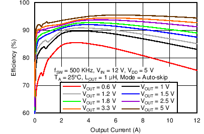
Efficiency
4 Revision History
Changes from A Revision (December 2013) to B Revision
- Added Pin Configuration and Functions section, Handling Rating table, Feature Description section, Device Functional Modes, Application and Implementation section, Power Supply Recommendations section, Layout section, Device and Documentation Support section, and Mechanical, Packaging, and Orderable Information section Go
Changes from * Revision (August 2013) to A Revision
5 Pin Configuration and Functions

Pin Functions
| PIN | I/O(1) | DESCRIPTION | |
|---|---|---|---|
| NAME | NO. | ||
| DNC | 26 | O | Do not connect. This pin is the output of unused internal circuitry and must be floating. |
| EN | 3 | I | The enable pin turns on the DC-DC switching converter. |
| FB | 23 | I | VOUT feedback input. Connect this pin to a resistor divider between the VOUT pin and GND. |
| GND | 22 | G | This pin is the ground of internal analog circuitry and driver circuitry. Connect GND to the PGND plane with a short trace (For example, connect this pin to the thermal pad with a single trace and connect the thermal pad to PGND pins and PGND plane). |
| GND1 | 27 | I | Connect this pin to ground. GND1 is the input of unused internal circuitry and must connect to ground. |
| GND2 | 28 | I | Connect this pin to ground. GND2 is the input of unused internal circuitry and must connect to ground. |
| MODE | 21 | I | The MODE pin sets the forced continuous-conduction mode (FCCM) or Skip-mode operation. It also selects the ramp coefficient of D-CAP3 mode. |
| NC | 5 | — | Not connected. These pins are floating internally. |
| 18 | |||
| PGND | 10 | G | These ground pins are connected to the return of the internal low-side MOSFET. |
| 11 | |||
| 12 | |||
| 13 | |||
| 14 | |||
| PGOOD | 2 | O | Open-drain power-good status signal which provides startup delay after the FB voltage falls within the specified limits. After the FB voltage moves outside the specified limits, PGOOD goes low within 2 µs. |
| RF | 1 | I | RF is the SW-frequency configuration pin. Connect this pin to a resistor divider between VREG and GND to program different SW frequency settings. |
| SW | 6 | I/O | SW is the output switching terminal of the power converter. Connect this pin to the output inductor. |
| 7 | |||
| 8 | |||
| 9 | |||
| TRIP | 25 | I/O | TRIP is the OCL detection threshold setting pin. ITRIP = 10 µA at room temp, 3000 ppm/°C current is sourced and sets the OCL trip voltage. See the Current Sense and Overcurrent Protection section for detailed OCP setting. |
| VBST | 4 | P | VBST is the supply rail for the high-side gate driver (boost terminal). Connect the bootstrap capacitor from this pin to the SW node. Internally connected to VREG via bootstrap PMOS switch. |
| VDD | 19 | P | Power-supply input pin for controller. Input of the VREG LDO. The input range is from 4.5 to 25 V. |
| VIN | 15 | P | VIN is the conversion power-supply input pins. |
| 16 | |||
| 17 | |||
| VREG | 20 | O | VREG is the 5-V LDO output. This voltage supplies the internal circuitry and gate driver. |
| VO | 24 | I | VOUT voltage input to the controller. |
6 Specifications
6.1 Absolute Maximum Ratings(1)
over operating free-air temperature range (unless otherwise noted)| MIN | MAX | UNIT | |||
|---|---|---|---|---|---|
| Input voltage range(2) | EN | –0.3 | 7.7 | V | |
| SW | DC | –3 | 30 | ||
| Transient < 10 ns | –5 | 32 | |||
| VBST | –0.3 | 36 | |||
| VBST(3) | –0.3 | 6 | |||
| VBST when transient < 10 ns | 38 | ||||
| VDD | –0.3 | 28 | |||
| VIN | –0.3 | 30 | |||
| VO, FB, MODE, RF | –0.3 | 6 | |||
| Output voltage range | PGOOD | –0.3 | 7.7 | V | |
| VREG, TRIP | –0.3 | 6 | |||
| Junction temperature, TJ | –40 | 150 | °C | ||
| Storage temperature, Tstg | –55 | 150 | °C | ||
6.2 ESD Ratings
| VALUE | UNIT | |||
|---|---|---|---|---|
| V(ESD) | Electrostatic discharge | Human-body model (HBM), per ANSI/ESDA/JEDEC JS-001(1) | ±2500 | V |
| Charged-device model (CDM), per JEDEC specification JESD22-C101(2) | ±1500 | |||
6.3 Recommended Operating Conditions
over operating free-air temperature range (unless otherwise noted)| MIN | MAX | UNIT | ||
|---|---|---|---|---|
| Input voltage | EN | –0.1 | 7 | V |
| SW | –3 | 27 | ||
| VBST | –0.1 | 28 | ||
| VBST(1) | –0.1 | 5.5 | ||
| VDD | 4.5 | 25 | ||
| VIN | 1.5 | 18 | ||
| VO, FB, MODE, RF | –0.1 | 5.5 | ||
| Output voltage | PGOOD | –0.1 | 7 | V |
| VREG, TRIP | –0.1 | 5.5 | ||
| Operating free-air temperature, TA | –40 | 85 | °C | |
6.4 Thermal Information
| THERMAL METRIC(1) | TPS53515 | UNIT | |
|---|---|---|---|
| RVE (VQFN-CLIP) |
|||
| 28 PINS | |||
| RθJA | Junction-to-ambient thermal resistance | 37.5 | °C/W |
| RθJC(top) | Junction-to-case (top) thermal resistance | 34.1 | °C/W |
| RθJB | Junction-to-board thermal resistance | 18.1 | °C/W |
| ψJT | Junction-to-top characterization parameter | 1.8 | °C/W |
| ψJB | Junction-to-board characterization parameter | 18.1 | °C/W |
| RθJC(bot) | Junction-to-case (bottom) thermal resistance | 2.2 | °C/W |
6.5 Electrical Characteristics
over operating free-air temperature range, VREG = 5 V, EN = 5 V (unless otherwise noted)| PARAMETER | TEST CONDITIONS | MIN | TYP | MAX | UNIT | |
|---|---|---|---|---|---|---|
| SUPPLY CURRENT | ||||||
| IVDD | VDD bias current | TA = 25°C, No load Power conversion enabled (no switching) |
1350 | 1850 | µA | |
| IVDDSTBY | VDD standby current | TA = 25°C, No load Power conversion disabled |
850 | 1150 | µA | |
| IVIN(leak) | VIN leakage current | VEN = 0 V | 0.5 | µA | ||
| VREF OUTPUT | ||||||
| VVREF | Reference voltage | FB w/r/t GND, TA = 25°C | 597 | 600 | 603 | mV |
| VVREFTOL | Reference voltage tolerance | FB w/r/t GND, 0°C ≤ TJ ≤ 85°C | –0.6% | 0.5% | ||
| FB w/r/t GND, =–40°C ≤ TJ ≤ 85°C | –0.7% | 0.5% | ||||
| OUTPUT VOLTAGE | ||||||
| IFB | FB input current | VFB = 600 mV | 50 | 100 | nA | |
| IVODIS | VO discharge current | VVO = 0.5 V, Power Conversion Disabled | 10 | 12 | 15 | mA |
| SMPS FREQUENCY | ||||||
| fSW | VO switching frequency(2) | VIN = 12 V, VVO = 3.3 V, RDR < 0.041 | 250 | kHz | ||
| VIN = 12 V, VVO = 3.3 V, RDR = 0.096 | 300 | |||||
| VIN = 12 V, VVO = 3.3 V, RDR = 0.16 | 400 | |||||
| VIN = 12 V, VVO = 3.3 V, RDR = 0.229 | 500 | |||||
| VIN = 12 V, VVO = 3.3 V, RDR = 0.297 | 600 | |||||
| VIN = 12 V, VVO = 3.3 V, RDR = 0.375 | 750 | |||||
| VIN = 12 V, VVO = 3.3 V, RDR = 0.461 | 850 | |||||
| VIN = 12 V, VVO = 3.3 V, RDR > 0.557 | 1000 | |||||
| tON(min) | Minimum on-time | TA = 25°C(1) | 60 | ns | ||
| tOFF(min) | Minimum off-time | TA = 25°C | 175 | 240 | 310 | ns |
| INTERNAL BOOTSTRAP SW | ||||||
| VF | Forward Voltage | VVREG–VBST, TA = 25°C, IF = 10 mA | 0.15 | 0.25 | V | |
| IVBST | VBST leakage current | TA = 25°C, VVBST = 33 V, VSW = 28 V | 0.01 | 1.5 | µA | |
| LOGIC THRESHOLD | ||||||
| VENH | EN enable threshold voltage | 1.3 | 1.4 | 1.5 | V | |
| VENL | EN disable threshold voltage | 1.1 | 1.2 | 1.3 | V | |
| VENHYST | EN hysteresis voltage | 0.22 | V | |||
| VENLEAK | EN input leakage current | –1 | 0 | 1 | µA | |
| SOFT START | ||||||
| tSS | Soft-start time | 1 | ms | |||
| PGOOD COMPARATOR | ||||||
| VPGTH | VDDQ PGOOD threshold | PGOOD in from higher | 104% | 108% | 111% | |
| PGOOD in from lower | 89% | 92% | 96% | |||
| PGOOD out to higher | 113% | 116% | 120% | |||
| PGOOD out to lower | 80% | 84% | 87% | |||
| IPG | PGOOD sink current | VPGOOD = 0.5 V | 4 | 6 | mA | |
| tPGDLY | PGOOD delay time | Delay for PGOOD going in | 0.8 | 1.0 | 1.2 | ms |
| Delay for PGOOD coming out | 2 | µs | ||||
| IPGLK | PGOOD leakage current | VPGOOD = 5 V | –1 | 0 | 1 | µA |
| CURRENT DETECTION | ||||||
| RTRIP | TRIP pin resistance range | 20 | 70 | kΩ | ||
| IOCL | Current limit threshold, valley | RTRIP = 52.3 kΩ | 10.1 | 12 | 13.9 | A |
| RTRIP = 38 kΩ | 7.2 | 9.1 | 11.0 | |||
| IOCLN | Negative current limit threshold, valley | RTRIP = 52.3 kΩ | –15.3 | –11.9 | –8.5 | A |
| RTRIP = 38 kΩ | –12 | –9 | –6 | |||
| VZC | Zero cross detection offset | 0 | mV | |||
| PROTECTIONS | ||||||
| VVREGUVLO | VREG undervoltage-lockout (UVLO) threshold voltage | Wake-up | 3.25 | 3.34 | 3.41 | V |
| Shutdown | 3.00 | 3.12 | 3.19 | |||
| VVDDUVLO | VDD UVLO threshold voltage | Wake-up (default) | 4.15 | 4.25 | 4.35 | V |
| Shutdown | 3.95 | 4.05 | 4.15 | |||
| VOVP | Overvoltage-protection (OVP) threshold voltage | OVP detect voltage | 116% | 120% | 124% | |
| tOVPDLY | OVP propagation delay | With 100-mV overdrive | 300 | ns | ||
| VUVP | Undervoltage-protection (UVP) threshold voltage | UVP detect voltage | 64% | 68% | 71% | |
| tUVPDLY | UVP delay | UVP filter delay | 1 | ms | ||
| THERMAL SHUTDOWN | ||||||
| TSDN | Thermal shutdown threshold(1) | Shutdown temperature | 140 | °C | ||
| Hysteresis | 40 | |||||
| LDO VOLTAGE | ||||||
| VREG | LDO output voltage | VIN = 12 V, ILOAD = 10 mA | 4.65 | 5 | 5.45 | V |
| VDOVREG | LDO low droop drop-out voltage | VIN = 4.5 V, ILOAD = 30 mA, TA = 25°C | 365 | mV | ||
| ILDOMAX | LDO overcurrent limit | VIN = 12 V, TA = 25°C | 170 | 200 | mA | |
| INTERNAL MOSFETS | ||||||
| RDS(on)H | High-side MOSFET on-resistance | TA = 25°C | 13.8 | 15.5 | mΩ | |
| RDS(on)L | Low-side MOSFET on-resistance | TA = 25°C | 5.9 | 7.0 | mΩ | |
6.6 Typical Characteristics

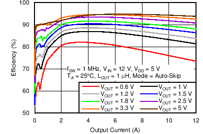
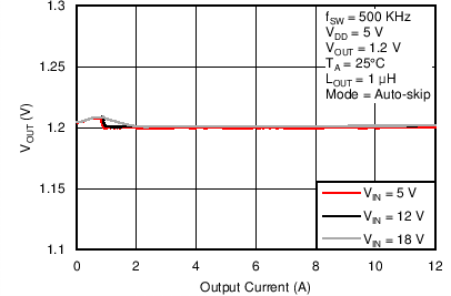
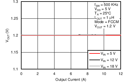
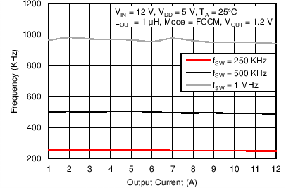
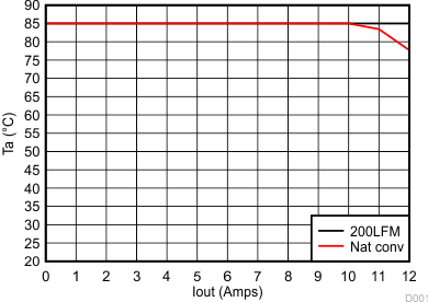
| VIN = 12 V | Switching frequency = 600kHz | |
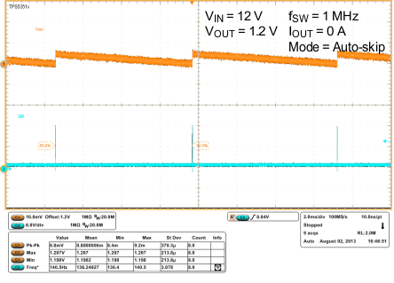
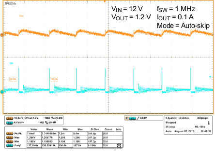
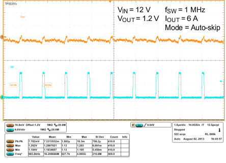
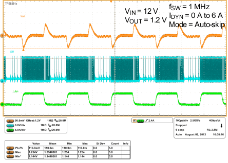
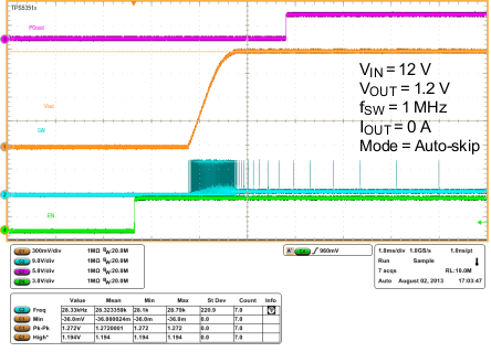
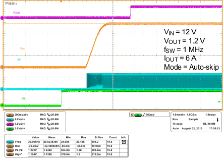
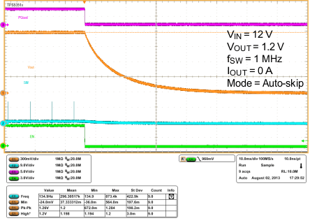
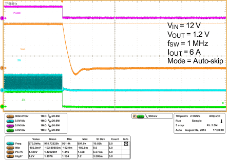
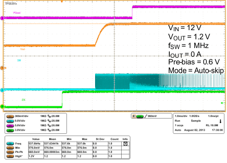
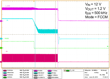
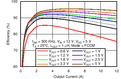
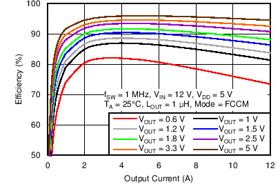
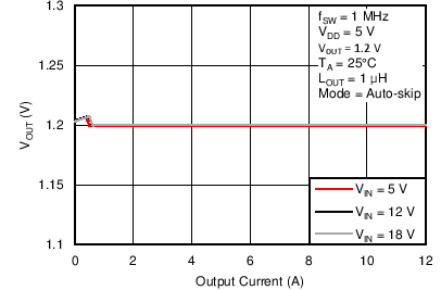
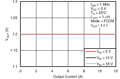
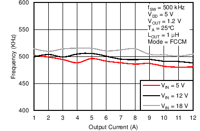
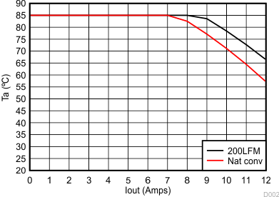
| VIN = 12 V | Switching frequency = 600kHz | |
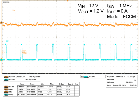
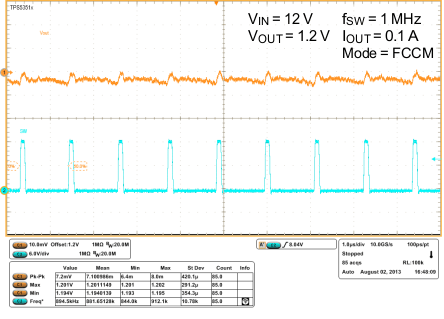
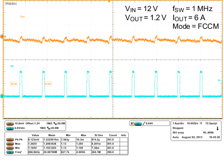
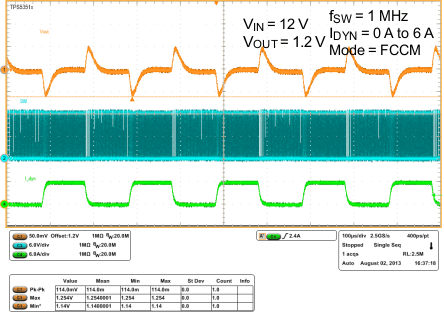
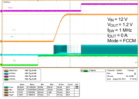
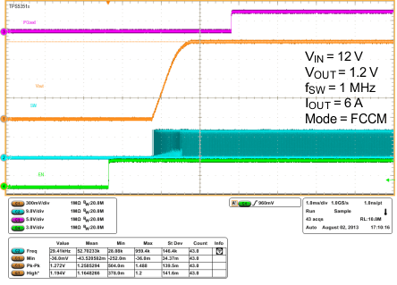
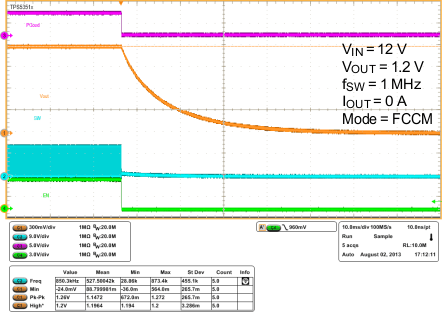
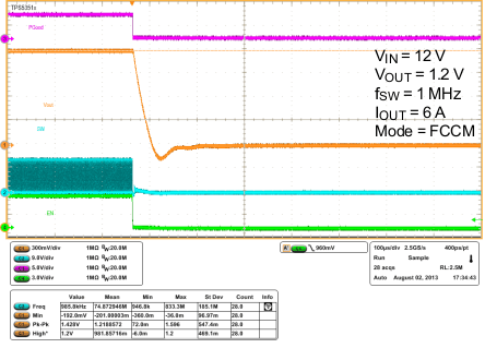
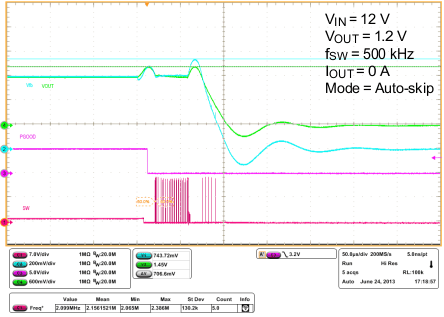
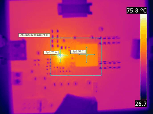
| fSW = 500 kHz | VI = 12 V | VO = 5 V |
| IO = 12 A | COUT= 10 x 22 µF | ( 1206, 6.3 V, X5R) |
| SNB = 3 Ω+ 470 pF | RBOOT= 0 Ω | |
| Inductor: | LOUT = 1 µH | 2.1 mΩ (typ) |
| PCMC135T-1R0MF | 12.6 mm × 13.8 mm × 5 mm | |