SLVSAD1B June 2010 – January 2016 TPS80010
PRODUCTION DATA.
- 1 Features
- 2 Applications
- 3 Description
- 4 Revision History
- 5 Pin Configuration and Functions
- 6 Specifications
- 7 Detailed Description
- 8 Application and Implementation
- 9 Power Supply Recommendations
- 10Layout
- 11Device and Documentation Support
- 12Mechanical, Packaging, and Orderable Information
Package Options
Mechanical Data (Package|Pins)
- RSM|32
Thermal pad, mechanical data (Package|Pins)
- RSM|32
Orderable Information
1 Features
- 1.8-V Buck DC-DC Converter
- 3.1-V Boost DC-DC Converter with 3-V Post-Regulation LDO
- Over 91% Conversion Efficiency
- Current-Limited Start-Up for Both DC-DC Converters
- Load Switch With Current-Limited Turnon
- Battery-Level Monitor Switch
- 32-Pin, 4-mm × 4-mm × 1-mm VQFN Package
- ESD Performance Tested per JESD 22
2 Applications
- Wireless Mice
- Wireless Keyboards
- Game Controllers
3 Description
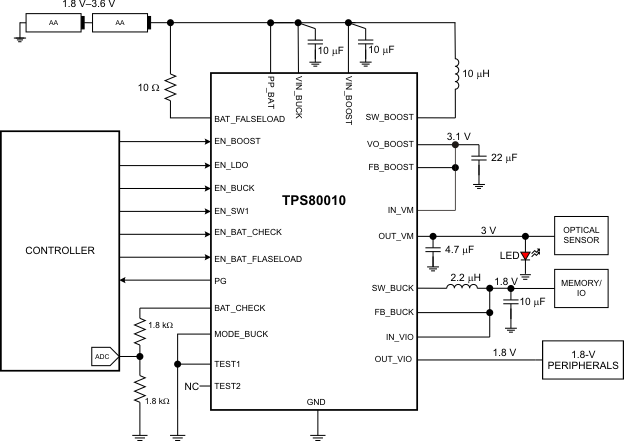
The TPS80010 device provides an integrated power-management solution for 2-cell alkaline battery applications such as wireless mice, keyboards, and video game controllers. The VBUCK 1.8-V output is powered by a buck converter with a load capacity of 100 mA. A Power Good (PG) signal is generated when VBUCK is greater than 90% of its target output voltage. Integrated in the TPS80010 is an 80-mΩ load switch that can be connected to the VBUCK output, allowing more system design flexibility when connecting to multiple loads. The 3.1-V VBOOST output is powered by a boost converter. The VBOOST output voltage is post-regulated by the integrated 3-V LDO. This post-regulation provides a low-noise supply level through the specified battery range.
Device Information(1)
| PART NUMBER | PACKAGE | BODY SIZE (NOM) |
|---|---|---|
| TPS80010 | VQFN (32) | 4.00 mm × 4.00 mm |
- For all available packages, see the orderable addendum at the end of the data sheet.
Typical Application
