SLVSDR2B November 2018 – March 2021 ADC12DJ3200QML-SP
PRODUCTION DATA
- 1 Features
- 2 Applications
- 3 Description
- 4 Revision History
- 5 Pin Configuration and Functions
-
6 Specifications
- 6.1 Absolute Maximum Ratings
- 6.2 ESD Ratings
- 6.3 Recommended Operating Conditions
- 6.4 Thermal Information
- 6.5 Electrical Characteristics: DC Specifications
- 6.6 Electrical Characteristics: Power Consumption
- 6.7 Electrical Characteristics: AC Specifications (Dual-Channel Mode)
- 6.8 Electrical Characteristics: AC Specifications (Single-Channel Mode)
- 6.9 Timing Requirements
- 6.10 Switching Characteristics
- 6.11 Timing Diagrams
- 6.12 Typical Characteristics
-
7 Detailed Description
- 7.1 Overview
- 7.2 Functional Block Diagram
- 7.3
Feature Description
- 7.3.1 Analog Inputs
- 7.3.2 ADC Core
- 7.3.3 Timestamp
- 7.3.4 Clocking
- 7.3.5 Digital Down Converters (Dual-Channel Mode Only)
- 7.3.6 JESD204B Interface
- 7.3.7 Alarm Monitoring
- 7.3.8 Temperature Monitoring Diode
- 7.3.9 Analog Reference Voltage
- 7.4
Device Functional Modes
- 7.4.1 Dual-Channel Mode
- 7.4.2 Single-Channel Mode (DES Mode)
- 7.4.3 JESD204B Modes
- 7.4.4 Power-Down Modes
- 7.4.5 Test Modes
- 7.4.6 Calibration Modes and Trimming
- 7.4.7 Offset Calibration
- 7.4.8 Trimming
- 7.4.9 Offset Filtering
- 7.5 Programming
- 7.6 Register Maps
- 8 Application Information Disclaimer
- 9 Layout
- 10Device and Documentation Support
Package Options
Refer to the PDF data sheet for device specific package drawings
Mechanical Data (Package|Pins)
- ZMX|196
- NWE|196
Thermal pad, mechanical data (Package|Pins)
Orderable Information
7.4.3.2 Dual DDC and Redundant Data Mode
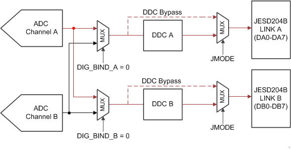
When operating in dual-channel mode, the data from one channel can be routed to both digital down-converter blocks by using DIG_BIND_A or DIG_BIND_B (see the digital channel binding register). This feature enables down-conversion of two separate captured bands from a single ADC channel. The second ADC can be powered down in this mode by setting PD_ACH or PD_BCH (see the device configuration register).
Additionally, DIG_BIND_A or DIG_BIND_B can be used to provide redundant data to separate digital processors by routing data from one ADC channel to both JESD204B links. Redundant data mode is available for all JMODE modes except for the single-channel modes. Both dual DDC mode and redundant data mode are demonstrated in Figure 7-21 where the data for ADC channel A is routed to both DDCs and then transmitted to a single processor or two processors (for redundancy).
 Figure 7-21 Dual DDC Mode or Redundant Data Mode for Channel A