-
ADC3910Dx and ADC3910Sx 10-bit, 25 to 125MSPS Low Latency, Low Power, Small, Single and Dual Channel ADC with Integrated Input Buffers SBASAD1A December 2023 – May 2024 ADC3910D025 , ADC3910D065 , ADC3910D125 , ADC3910S025 , ADC3910S065 , ADC3910S125
PRODUCTION DATA
-
ADC3910Dx and ADC3910Sx 10-bit, 25 to 125MSPS Low Latency, Low Power, Small, Single and Dual Channel ADC with Integrated Input Buffers
- 1
- 1 Features
- 2 Applications
- 3 Description
- 4 Pin Configuration and Functions
-
5 Specifications
- 5.1 Absolute Maximum Ratings
- 5.2 ESD Ratings
- 5.3 Recommended Operating Conditions
- 5.4 Thermal Information
- 5.5 Electrical Characteristics - Power Consumption
- 5.6 Electrical Characteristics - DC Specifications
- 5.7 Electrical Characteristics - AC Specifications (25 MSPS)
- 5.8 Electrical Characteristics - AC Specifications (65 MSPS)
- 5.9 Electrical Characteristics - AC Specifications (125 MSPS)
- 5.10 Timing Requirements
- 5.11 Output Interface Timing Diagram
- 5.12 Typical Characteristics - 25MSPS
- 5.13 Typical Characteristics - 65MSPS
- 5.14 Typical Characteristics - 125MSPS
-
6 Detailed Description
- 6.1 Overview
- 6.2 Functional Block Diagram
- 6.3 Feature Description
- 6.4 Device Functional Modes
- 6.5 Programming
- 6.6 Register Maps
- 7 Application Information Disclaimer
- 8 Device and Documentation Support
- 9 Revision History
- 10Mechanical, Packaging, and Orderable Information
- IMPORTANT NOTICE
Package Options
Mechanical Data (Package|Pins)
- RSM|32
Thermal pad, mechanical data (Package|Pins)
- RSM|32
Orderable Information
ADC3910Dx and ADC3910Sx 10-bit, 25 to 125MSPS Low Latency, Low Power, Small, Single and Dual Channel ADC with Integrated Input Buffers
1 Features
- Sampling rate up to 125MSPS
- Latency: 1 clock cycle
- Low power (2 channel):
- 92mW at 125MSPS
- 59mW at 25MSPS
- 4mW in PD mode
- Small footprint: 32-VQFN (4mm x 4mm)
- Single or dual channel ADC
- Dual digital comparators
- Reference: internal or external
- No missing codes, ±1 LSB INL
- Buffered, differential or single ended inputs
- Input bandwidth: 150MHz (3-dB)
- Single 1.8V supply
- Optional 3.3VIO capability
- Industrial temperature range: -40 to 105°C
- On-chip digital filter
(optional)
- Decimation by 2, 4, 8, 16
- Parallel (SDR, DDR) and serial CMOS interface
- Spectral performance
(fIN = 5MHz):
- SNR: 61dBFS
- SFDR: 65dBc
2 Applications
- Radio receiver
- LiDAR
- Low latency control loops
- Laser scanners
- Global positioning systems
- Source measure unit
- Detection equipment
3 Description
The ADC3910Dx and ADC3910Sx are a family ultra-low power 10-bit 125MSPS high-speed single and dual channel analog-to-digital converters. High-speed control loops benefit from the short latency of only 1 clock cycle. The ADC consumes only 92mW at 125Msps with a power consumption that scales with lower sampling rates.
The device uses DDR, HDDR, SDR or serial CMOS interface to output the data from +1.8V to +3.3V to accommodate various receiver requirements. The device implements analog monitoring function by event triggered interrupts per channel using a digital comparator with programmable high and low thresholds, hysteresis, and event counter. The device is a pin-to-pin compatible family of ADCs with 8 and 10-bit resolution and different speed grades. The device is available in a 32-pin VQFN package, and supports industrial temperature range from -40 to +105°C.
| PART NUMBER | PACKAGE(1) | PACKAGE SIZE(2) |
|---|---|---|
| ADC3910D025, 'D065, 'D125 ADC3910S025,'S065, 'S125 | VQFN (32) | 4mm × 4mm |
| PART NUMBER (c= #CH; sss= MSPS) | RESOLUTION | SAMPLING RATE MSPS |
|---|---|---|
| ADC3910csss | 10-Bit | 25, 65, 125 |
| ADC3908csss | 08-Bit | 25, 65, 125 |
 Block Diagram
4 Pin Configuration and Functions
| PIN | TYPE | DESCRIPTION | |
|---|---|---|---|
| NAME | NO. | ||
| INPUT or REFERENCE | |||
| INAP | 10 | I | Positive analog input, channel A |
| INAM | 11 | I | Negative analog input, channel A |
| INBP/NC | 14 | I | Positive analog input, channel B (NC on single channel device) |
| INBM/NC | 15 | I | Negative analog input, channel B (NC on single channel device) |
| VREF | 17 | I | 1.2V external voltage reference input. A 10μF and a 0.1μF ceramic bypass capacitor connected between VREF and GND pins and placed as close to the pins as possible is recommended when using external reference. Otherwise, connect to GND when using internal reference. |
| VCM | 7 | O | Common-mode voltage output to provide DC bias for the analog inputs, 1.25V |
| CLOCK | |||
| CLK | 8 | I | Sampling clock input for the ADC |
| CONFIGURATION | |||
| RESET | 9 | I | Hardware reset. Active high. This pin has an internal 60kΩ pull-down resistor. |
| SEN | 16 | I | Serial interface enable, Active low, internal 40kΩ pull-down resistor. |
| SCLK | 18 | I | Serial interface clock input, internal 40kΩ pull-down resistor. |
| SDIO | 19 | I/O | Serial interface data input and output, internal 40kΩ pull-down resistor. |
| ALERT | 20 | O | Digital window comparator status pin or over range alert. |
| DIGITAL INTERFACE | |||
| D0 | 4 | O | CMOS digital lane output data. |
| D1 | 3 | O | |
| D2 | 2 | O | |
| D3 | 1 | O | |
| D4 | 32 | O | |
| D5 | 31 | O | |
| D6 | 26 | O | |
| D7 | 25 | O | |
| D8 | 24 | O | |
| D9 | 23 | O | |
| D10 | 22 | O | |
| D11 | 21 | O | |
| DCLK | 30 | O | CMOS output for data bit clock. |
| DCLK/FCLK | 29 | O | Default is Inverse data bit clock for CMOS output data. Frame clock can be selected via SPI write |
| OEN/PD | 6 | I | Output data enable. This pin is active low with default 60kΩ pull-down. Can be configured as power down pin through SPI. |
| POWER SUPPLY | |||
| AVDD | 12, 13 | I | Analog 1.8V power supply |
| GND | PowerPAD™ | I | Analog Ground, 0V |
| IOVDD | 27 | I | 1.8V to 3.3V power supply for digital interface |
| DGND | 28 | I | Ground, 0V for digital interface |
OTHER | |||
| NC | 17 | N/A | No connection. Connect to ground |
5 Specifications
5.1 Absolute Maximum Ratings
| PARAMETER | TEST CONDITIONS | MIN | MAX | UNIT |
|---|---|---|---|---|
| Supply voltage range 1.8 V, AVDD | –0.3 | 2.1 | V | |
| Supply voltage range 1.8 V to 3.3 V, IOVDD | –0.3 | 3.6 | ||
| Supply voltage range, GND, DGND | –0.3 | 0.3 | ||
| Voltage applied to input pins | INAP/M, INBP/M, CLK, DCLKIN | –0.3 | 2.1 | |
| VREF | –0.3 | 2.1 | ||
| RESET, SCLK, SEN, SDIO, OEN | –0.3 | 2.1 | ||
| Junction temperature, TJ | 110 | °C | ||
| Storage temperature, Tstg | –65 | 150 | °C | |
5.2 ESD Ratings
| VALUE | UNIT | |||
|---|---|---|---|---|
| V(ESD) | Electrostatic discharge | Human body model (HBM), per ANSI/ESDA/JEDEC JS-001, all pins(1) | 1000 | V |
| Charged device model (CDM), per ANSI/ESDA/JEDEC JS-002, all pins(2) | 500 | |||
5.3 Recommended Operating Conditions
| MIN | NOM | MAX | UNIT | |||
|---|---|---|---|---|---|---|
| Supply voltage range | Supply voltage range 1.8v | AVDD(1) | 1.7 | 1.8 | 1.9 | V |
| Supply voltage range | IOVDD(1) | 1.7 | 1.8 | 1.9 | V | |
| Supply voltage range | Supply voltage range 3.3v | IOVDD(1) | 3.2 | 3.3 | 3.4 | V |
| TA | Operating free-air temperature | –40 | 105 | °C | ||
| TJ | Operating junction temperature | 105(2) | °C | |||
5.4 Thermal Information
| THERMAL METRIC(1) | ADC39xx | UNIT | |
|---|---|---|---|
| RSM (QFN) | |||
| 32 Pins | |||
| RΘJA | Junction-to-ambient thermal resistance | 38.1 | °C/W |
| RΘJC(top) | Junction-to-case (top) thermal resistance | 37.2 | °C/W |
| RΘJB | Junction-to-board thermal resistance | 17.9 | °C/W |
| ΨJT | Junction-to-top characterization parameter | 1 | °C/W |
| ΨJB | Junction-to-board characterization parameter | 17.9 | °C/W |
| RΘJC(bot) | Junction-to-case (bottom) thermal resistance | 7.8 | °C/W |
5.5 Electrical Characteristics - Power Consumption
| PARAMETER | TEST CONDITIONS | MIN | TYP | MAX | UNIT | |
|---|---|---|---|---|---|---|
| ADC3910D025 | ||||||
| IAVDD | Analog supply current | FS = 25 MSPS, dual channel | 29 | 31 | mA | |
| IIOVDD | Digital supply current | 4 | 9 | mA | ||
| PDIS | Power dissipation | 59 | mW | |||
| ADC3910S025 | ||||||
| IAVDD | Analog supply current | FS = 25 MSPS, single channel | 19 | 22 | mA | |
| IIOVDD | Digital supply current | 4 | 8 | mA | ||
| PDIS | Power dissipation | 41 | mW | |||
| ADC3910D065 | ||||||
| IAVDD | Analog supply current | FS = 65 MSPS, dual channel | 33 | 36 | mA | |
| IIOVDD | Digital supply current | 9 | 18 | mA | ||
| PDIS | Power dissipation | 76 | mW | |||
| ADC3910S065 | ||||||
| IAVDD | Analog supply current | FS = 65 MSPS, single channel | 22 | 24 | mA | |
| IIOVDD | Digital supply current | 10 | 19 | mA | ||
| PDIS | Power dissipation | 58 | mW | |||
| ADC3910D125 | ||||||
| IAVDD | Analog supply current | FS = 125 MSPS, dual channel | 39 | 44 | mA | |
| IIOVDD | Digital supply current | 15 | 18.5 | mA | ||
| PDIS | Power dissipation | 97 | mW | |||
| ADC3910S125 | ||||||
| IAVDD | Analog supply current | FS = 125 MSPS, single channel | 25 | 28 | mA | |
| IIOVDD | Digital supply current | 19 | 32 | mA | ||
| PDIS | Power dissipation | 80 | mW | |||
| Power down | ||||||
| PDIS | Power consumption in global power down mode | 4 | mW | |||
5.6 Electrical Characteristics - DC Specifications
| PARAMETER | TEST CONDITIONS | MIN | TYP | MAX | UNIT | |
|---|---|---|---|---|---|---|
| DC ACCURACY (25 MSPS) | ||||||
| No missing codes | No missing codes | 10 | bits | |||
| DNL | Differential nonlinearity | -0.95 | ±0.4 | 2.1 | LSB | |
| INL | Integral nonlinearity | -2 | ±0.5 | 2.1 | LSB | |
| VOS_ERR | Offset error | -2.75 | ±1 | 2.75 | LSB | |
| VOS_DRIFT | Offset drift over temperature | 0.001 | LSB/ºC | |||
| GAINERR | Gain error | External Reference | -2.25 | ±0.2 | 2.25 | %FSR |
| Internal Reference | ±0.8 | %FSR | ||||
| GAINDRIFT | Gain drift over temperature | External Reference | -35 | ppm/ºC | ||
| Internal Reference | -102 | ppm/ºC | ||||
| DC ACCURACY (65 MSPS) | ||||||
| No missing codes | No missing codes | 10 | bits | |||
| DNL | Differential nonlinearity | -0.95 | ±0.4 | 2.1 | LSB | |
| INL | Integral nonlinearity | -2 | ±0.5 | 2.1 | LSB | |
| VOS_ERR | Offset error | -2.75 | ±1 | 2.75 | LSB | |
| VOS_DRIFT | Offset drift over temperature | 0.001 | LSB/ºC | |||
| GAINERR | Gain error | External Reference | -2.25 | ±0.2 | 2.25 | %FSR |
| Internal Reference | ±0.8 | %FSR | ||||
| GAINDRIFT | Gain drift over temperature | External Reference | -35 | ppm/ºC | ||
| Internal Reference | -102 | ppm/ºC | ||||
| DC ACCURACY (125 MSPS) | ||||||
| No missing codes | No missing codes | 10 | bits | |||
| DNL | Differential nonlinearity | -0.95 | ±0.4 | 2.1 | LSB | |
| INL | Integral nonlinearity | -2 | ±0.5 | 2.1 | LSB | |
| VOS_ERR | Offset error | -2.75 | ±1 | 2.75 | LSB | |
| VOS_DRIFT | Offset drift over temperature | 0.001 | LSB/ºC | |||
| GAINERR | Gain error | External Reference | -2.25 | ±0.3 | 2.25 | %FSR |
| Internal Reference | ±0.8 | %FSR | ||||
| GAINDRIFT | Gain drift over temperature | External Reference | -35 | ppm/ºC | ||
| Internal Reference | -102 | ppm/ºC | ||||
| ADC ANALOG INPUT (INAP/M, INBP/M) | ||||||
| FS | Input full scale | Differential | 1.9 | Vpp | ||
| Single-ended | 0.95 | Vpp | ||||
| CIN | Differential input Capacitance | FIN = 100 kHz | 7 | pF | ||
| VCM | Input common mode voltage | VOCM - 50mV | 1.275 | VOCM + 50mV | V | |
| VOCM | Output common mode voltage | 1.25 | V | |||
| BW | Analog Input Bandwidth (-3dB) | 150 | MHz | |||
| EXTERNAL VOLTAGE REFERENCE (VREF) | ||||||
| VREF | External voltage reference | 1.2 | V | |||
| Input Current | 0.1 | mA | ||||
| Input impedance | 12 | kΩ | ||||
| CLOCK INPUT | ||||||
| Input clock frequency | 5 | 125 | MHz | |||
| VIH | High level input voltage | AVDD - 0.3 | 1.8 | V | ||
| VIL | Low level input voltage | 0 | AVSS + 0.3 | V | ||
| CIN | Input capacitance | 0.5 | pF | |||
| Clock duty cycle | 45 | 50 | 55 | % | ||
| DIGITAL INPUTS (DCLKIN, RESET, OEN, SCLK, SEN, SDIO) | ||||||
| VIH | High level input voltage | DCLKIN | AVDD - 0.1 | AVDD | V | |
| VIL | Low level input voltage | 0.1 | V | |||
| VIH | High level input voltage | RESET, OEN, SCLK, SEN, SDIO | 1.4 | V | ||
| VIL | Low level input voltage | 0.4 | V | |||
| IIH | High level input current | 90 | 150 | uA | ||
| IIL | Low level input current | -150 | -90 | uA | ||
| CI | Input capacitance | 1.5 | pF | |||
| DIGITAL OUTPUT (SDOUT) | ||||||
| VOH | High level output voltage | ILOAD = -400 uA | AVDD - 0.1 | AVDD | V | |
| VOL | Low level output voltage | ILOAD = 400 uA | 0.1 | V | ||
| DIGITAL CMOS OUTPUTS (D0:D11) | ||||||
| Output data rate | per CMOS output pin | 250 | MHz | |||
| VOH | High level output voltage | ILOAD = -400 uA | IOVDD - 0.1 | IOVDD | V | |
| VOL | Low level output voltage | ILOAD = 400 uA | 0.1 | V | ||
| VOH | High level output voltage | ILOAD = -400 uA, ALERT/GPO | IOVDD - 0.1 | IOVDD | V | |
| VOL | Low level output voltage | 0.1 | V | |||
5.7 Electrical Characteristics - AC Specifications (25 MSPS)
| PARAMETER | TEST CONDITIONS | MIN | TYP | MAX | UNIT | |
|---|---|---|---|---|---|---|
| NSD | Noise Spectral Density | fIN = 10 MHz, AIN = -20 dBFS | -132 | dBFS/Hz | ||
| SNR | Signal to noise ratio, excluding DC, HD2 to HD5 | fIN = 1.1 MHz | 61.1 | dBFS | ||
| fIN = 5 MHz | 57 | 60.7 | ||||
| fIN = 10 MHz | 61.1 | |||||
| fIN = 20 MHz | 61.0 | |||||
| SINAD | Signal to noise and distortion ratio, excluding DC offset | fIN = 1.1 MHz | 59.1 | dBFS | ||
| fIN = 5 MHz | 59.9 | |||||
| fIN = 10 MHz | 59.7 | |||||
| fIN = 20 MHz | 59.8 | |||||
| ENOB | Effective number of bits, excluding DC offset | fIN = 1.1 MHz | 9.9 | Bit | ||
| fIN = 5 MHz | 9.9 | |||||
| fIN = 10 MHz | 9.8 | |||||
| fIN = 20 MHz | 9.8 | |||||
| THD | Total Harmonic Distortion (First five harmonics) | fIN = 1.1 MHz | -62 | dBc | ||
| fIN = 5 MHz | -65 | |||||
| fIN = 10 MHz | -65 | |||||
| fIN = 20 MHz | -65 | |||||
| SFDR | Spur free dynamic range including second and third harmonic | fIN = 1.1 MHz | 63 | dBFS | ||
| fIN = 5 MHz | 57 | 66 | ||||
| fIN = 10 MHz | 65 | |||||
| fIN = 20 MHz | 65 | |||||
| SPUR | Spur free dynamic range (excluding DC, HD2, HD3) | fIN = 1.1 MHz | 83 | dBFS | ||
| fIN = 5 MHz | 58 | 85 | ||||
| fIN = 10 MHz | 85 | |||||
| fIN = 20 MHz | 82 | |||||
| IMD3 | Two tone inter-modulation distortion | fIN = 10/12 MHz, AIN = -7 dBFS/tone | -98 | dBc | ||
| XTALK | Channel-to-channel crosstalk | Aggressor = 1.1 MHz | 107 | dBFS | ||
| Aggressor = 10 MHz | 97 | |||||
| Aggressor = 20 MHz | 93 | |||||
5.8 Electrical Characteristics - AC Specifications (65 MSPS)
| PARAMETER | TEST CONDITIONS | MIN | TYP | MAX | UNIT | |
|---|---|---|---|---|---|---|
| NSD | Noise Spectral Density | fIN = 10 MHz, AIN = -20 dBFS | -135.9 | dBFS/Hz | ||
| SNR | Signal to noise ratio, excluding DC, HD2 to HD5 | fIN = 1.1 MHz | 61.0 | dBFS | ||
| fIN = 5 MHz | 57 | 61.1 | ||||
| fIN = 10 MHz | 61.1 | |||||
| fIN = 20 MHz | 61.1 | |||||
| fIN = 40 MHz | 61.0 | |||||
| fIN = 70 MHz | 60.7 | |||||
| SINAD | Signal to noise and distortion ratio, excluding DC offset | fIN = 1.1 MHz | 59.2 | dBFS | ||
| fIN = 5 MHz | 59.7 | |||||
| fIN = 10 MHz | 59.8 | |||||
| fIN = 20 MHz | 60.0 | |||||
| fIN = 40 MHz | 59.5 | |||||
| fIN = 70 MHz | 58.5 | |||||
| ENOB | Effective number of bits, excluding DC offset | fIN = 1.1 MHz | 9.8 | Bit | ||
| fIN = 5 MHz | 9.9 | |||||
| fIN = 10 MHz | 9.9 | |||||
| fIN = 20 MHz | 9.8 | |||||
| fIN = 40 MHz | 9.8 | |||||
| fIN = 70 MHz | 9.8 | |||||
| THD | Total Harmonic Distortion (First five harmonics) | fIN = 1.1 MHz | -62 | dBc | ||
| fIN = 5 MHz | -64 | |||||
| fIN = 10 MHz | -65 | |||||
| fIN = 20 MHz | -66 | |||||
| fIN = 40 MHz | -64 | |||||
| fIN = 70 MHz | -62 | |||||
| SFDR | Spur free dynamic range including second and third harmonic | fIN = 1.1 MHz | 63 | dBFS | ||
| fIN = 5 MHz | 57 | 65 | ||||
| fIN = 10 MHz | 65 | |||||
| fIN = 20 MHz | 66 | |||||
| fIN = 40 MHz | 64 | |||||
| fIN = 70 MHz | 62 | |||||
| SPUR | Spur free dynamic range (excluding DC, HD2, HD3) | fIN = 1.1 MHz | 85 | dBFS | ||
| fIN = 5 MHz | 58 | 85 | ||||
| fIN = 10 MHz | 85 | |||||
| fIN = 20 MHz | 82 | |||||
| fIN = 40 MHz | 77 | |||||
| fIN = 70 MHz | 71 | |||||
| IMD3 | Two tone inter-modulation distortion | fIN = 10/12 MHz, AIN = -7 dBFS/tone | -94 | dBc | ||
| XTALK | Channel-to-channel crosstalk | Aggressor = 1.1 MHz | 105 | dBFS | ||
| Aggressor = 10 MHz | 102 | |||||
| Aggressor = 20 MHz | 97 | |||||
5.9 Electrical Characteristics - AC Specifications (125 MSPS)
| PARAMETER | TEST CONDITIONS | MIN | TYP | MAX | UNIT | |
|---|---|---|---|---|---|---|
| NSD | Noise Spectral Density | fIN = 10 MHz, AIN = -20 dBFS | -138.8 | dBFS/Hz | ||
| SNR | Signal to noise ratio, excluding DC, HD2 to HD5 | fIN = 1.1 MHz | 60.8 | dBFS | ||
| fIN = 5 MHz | 57 | 60.6 | ||||
| fIN = 10 MHz | 60.6 | |||||
| fIN = 20 MHz | 60.6 | |||||
| fIN = 40 MHz | 60.6 | |||||
| fIN = 70 MHz | 60.4 | |||||
| SINAD | Signal to noise and distortion ratio, excluding DC offset | fIN = 1.1 MHz | 58.5 | dBFS | ||
| fIN = 5 MHz | 58.9 | |||||
| fIN = 10 MHz | 59.1 | |||||
| fIN = 20 MHz | 59.1 | |||||
| fIN = 40 MHz | 59.6 | |||||
| fIN = 70 MHz | 57.7 | |||||
| ENOB | Effective number of bits, excluding DC offset | fIN = 1.1 MHz | 9.8 | Bit | ||
| fIN = 5 MHz | 9.8 | |||||
| fIN = 10 MHz | 9.8 | |||||
| fIN = 20 MHz | 9.8 | |||||
| fIN = 40 MHz | 9.8 | |||||
| fIN = 70 MHz | 9.7 | |||||
| THD | Total Harmonic Distortion (First five harmonics) | fIN = 1.1 MHz | -61 | dBc | ||
| fIN = 5 MHz | -63 | |||||
| fIN = 10 MHz | -63 | |||||
| fIN = 20 MHz | -64 | |||||
| fIN = 40 MHz | -65 | |||||
| fIN = 70 MHz | -60 | |||||
| SFDR | Spur free dynamic range including second and third harmonic | fIN = 1.1 MHz | 62 | dBFS | ||
| fIN = 5 MHz | 57 | 64 | ||||
| fIN = 10 MHz | 64 | |||||
| fIN = 20 MHz | 65 | |||||
| fIN = 40 MHz | 67 | |||||
| fIN = 70 MHz | 61 | |||||
| SPUR | Spur free dynamic range (excluding DC, HD2, HD3) | fIN = 1.1 MHz | 84 | dBFS | ||
| fIN = 5 MHz | 58 | 82 | ||||
| fIN = 10 MHz | 84 | |||||
| fIN = 20 MHz | 82 | |||||
| fIN = 40 MHz | 78 | |||||
| fIN = 70 MHz | 75 | |||||
| IMD3 | Two tone inter-modulation distortion | fIN = 10/12 MHz, AIN = -7 dBFS/tone | -84 | dBc | ||
| fIN = 90/92 MHz, AIN = -7 dBFS/tone | -97 | |||||
| XTALK | Channel-to-channel crosstalk | Aggressor = 1.1 MHz | 102 | dBFS | ||
| Aggressor = 10 MHz | 90 | |||||
| Aggressor = 20 MHz | 98 | |||||
5.10 Timing Requirements
| PARAMETER | TEST CONDITIONS | MIN | NOM | MAX | UNIT | |
|---|---|---|---|---|---|---|
| ADC TIMING SPECIFICATIONS | ||||||
| tAD | Aperture Delay | 0.5 | ns | |||
| tA | Aperture Jitter | square wave clock with fast edges | 500 | fs | ||
| tACQ | Signal acquisition period, referenced to sampling clock falling edge | -TS/5 | Sampling Clock Period | |||
| tCONV | Signal conversion period, referenced to sampling clock falling edge | Fs = 25 MSPS | 5.5 | ns | ||
| Fs = 65 MSPS | 5.5 | ns | ||||
| Fs = 125 MSPS | 5.5 | ns | ||||
| Wake up time | Time to valid data after coming out of power down. Internal reference. | 30 | us | |||
| Time to valid data after coming out of power down. External 1.2V reference. | 19 | us | ||||
| ADC Latency | Signal input to data output | Low Latency Mode(1) | 1 | ADC clock cycles | ||
| Digital features enabled (includes Serial CMOS interface modes) | 5 | |||||
| Add. Latency | Real Decimation | 2 | 25 | |||
| 4 | 60 | |||||
| 8 | 130 | |||||
| 16 | 270 | |||||
| INTERFACE TIMING - DDR CMOS | ||||||
| tPD | Propagation delay: sampling clock falling edge to DCLK rising edge | TS/4 + 3 | ns | |||
| tDE | DCLK edge to previous data transition | Fs = 25 MSPS | -10 | -9 | ||
| Fs = 65 MSPS | -3.8 | -3.4 | ||||
| Fs = 125 MSPS | -2 | -1.8 | ||||
| tDL | DCLK edge to next data transition | Fs = 25 MSPS | 9 | 10 | ||
| Fs = 65 MSPS | 3.4 | 3.8 | ||||
| Fs = 125 MSPS | 1.8 | 2 | ||||
| INTERFACE TIMING - SDR CMOS | ||||||
| tPD | Propagation delay: sampling clock falling edge to DCLK rising edge | TS/4 + 3 | ns | |||
| tDE | DCLK edge to previous data transition | Fs = 25 MSPS | -20 | -18 | ||
| Fs = 65 MSPS | -7.6 | -6.9 | ||||
| Fs = 125 MSPS | -4 | -3.6 | ||||
| tDV | DCLK edge to next data transition | Fs = 25 MSPS | 18 | 20 | ||
| Fs = 65 MSPS | 6.9 | 7.7 | ||||
| Fs = 125 MSPS | 3.6 | 4 | ||||
| tPD | Propagation delay: sampling clock falling edge to output data delay | Delay between sampling clock falling edge to DCLKIN falling edge < 2.5ns. TDCLK = DCLK period tCDCLK = Sampling clock falling edge to DCLKIN falling edge |
TS/4 + 3 | ns | ||
| Delay between sampling clock falling edge to DCLKIN falling edge >= 2.5ns. TDCLK = DCLK period tCDCLK = Sampling clock falling edge to DCLKIN falling edge |
TS/4 + 3 | |||||
| tCD | DCLK rising edge to output data delay 4 Lane serial CMOS |
Fout = 10 MSPS | -7.25 | -6.25 | -5.25 | ns |
| Fout = 20 MSPS | -4.125 | -3.125 | -2.125 | |||
| Fout = 30 MSPS | -3.08 | -2.08 | -1.08 | |||
| DCLK rising edge to output data delay 2 Lane serial CMOS |
Fout = 5 MSPS | -7.25 | -6.25 | -5.25 | ||
| Fout = 10 MSPS | -4.125 | -3.125 | -2.125 | |||
| Fout = 15 MSPS | -3.08 | -2.08 | -1.08 | |||
| tDV | Data valid, 4 Lane serial CMOS | Fout = 10 MSPS | -7.25 | -6.25 | -5.25 | ns |
| Fout = 20 MSPS | -4.125 | -3.125 | -2.125 | |||
| Fout = 30 MSPS | -3.08 | -2.08 | -1.08 | |||
| Data valid, 2 Lane serial CMOS | Fout = 5 MSPS | -7.25 | -6.25 | -5.25 | ||
| Fout = 10 MSPS | -4.125 | -3.125 | -2.125 | |||
| Fout = 15 MSPS | -3.08 | -2.08 | -1.08 | |||
| SERIAL PROGRAMMING INTERFACE (SCLK, SEN, SDIO) - Input | ||||||
| fCLK,SCLK | Serial clock frequency | 20 | MHz | |||
| tS,SEN | SEN falling edge to SCLK rising edge | 10 | ns | |||
| tH,SEN | SCLK rising edge to SEN rising edge | 10 | ||||
| tS,SDIO | SDIO setup time from rising edge of SCLK | 17 | ||||
| tH,SDIO | SDIO hold time from rising edge of SCLK | 9 | ||||
| SERIAL PROGRAMMING INTERFACE (SDIO) - Output | ||||||
| tOZD | Delay from falling edge of 8th SCLK cycle during read operation for SDIO transition from tri-state to valid data | 3.9 | 10.8 | ns | ||
| tODZ | Delay from SEN rising edge for SDIO transition from valid data to tri-state | 3.4 | 14 | |||
| tOD | Delay from falling edge of 8th SCLK cycle during read operation to SDIO valid | 3.9 | 10.8 | |||
5.11 Output Interface Timing Diagram
 Figure 5-1 Timing Diagram: 10-Bit DDR (Default: 10 Lanes)
 Figure 5-2 Timing Diagram: 10-Bit SDR
(Default: 10 Lanes)
 Figure 5-3 Timing Diagram: 12-Bit DDR (Default: 10 Lanes)
 Figure 5-4 Timing Diagram: 12-Bit SDR (Default: 10 Lanes)
5.12 Typical Characteristics - 25MSPS
Typical values at TA = 25°C, ADC sampling rate = 25MSPS, AIN = –1dBFS, differential input, AVDD = IOVDD = 1.8V, internal 1.2V voltage reference, unless otherwise noted.

| SNR = 61.2dBFS, SFDR = 64dBc, Non HD23 = 84dBFS |

| SNR = 61dBFS, SFDR = 65dBc, Non HD23 = 87dBFS |

| AIN = -7dBFS/tone, IMD3 = -98dBc |

| FIN = 1MHz |
 Figure 5-13 Crosstalk vs Input Frequency
| FIN = 1MHz |

| FIN = 5MHz |

| Pulse Input = 1MHz |

| FIN = 1MHz, 16 bit resolution, DDR, 8 Output Lanes |

| FIN = 5MHz |

| SNR = 59dBFS, SFDR = 63dBc, Non HD23 = 85dBFS |

| SNR = 61.2dBFS, SFDR = 63dBc, Non HD23 = 83dBFS |
 Figure 5-10 AC
Performance vs Input Frequency
| FIN = 1MHz |

| FIN = 1MHz |

| FIN = 5MHz |
 Figure 5-18 DC
Offset Histogram
| FIN = 5MHz, DDC Bypass |

| FIN = 5MHz, DDR Interface Mode |
5.13 Typical Characteristics - 65MSPS
Typical values at TA = 25°C, ADC sampling rate = 65 MSPS, AIN = –1dBFS, differential input, AVDD = IOVDD = 1.8V, internal 1.2V voltage reference, unless otherwise noted.

| SNR = 61dBFS, SFDR = 64dBc, Non-HD23 = 88dBFS |

| SNR = 61dBFS, SFDR = 66dBc, Non-HD23 = 85dBFS |

| SNR = 60.9dBFS, SFDR = 64dBc, Non-HD23 = 79dBFS |
 Figure 5-30 AC
Performance vs Input Frequency
| FIN = 5MHz |

| FIN = 5MHz |

| FIN = 5MHz |
 Figure 5-38 DC
Offset Histogram
| FIN = 5MHz, DDC Bypass |

| FIN = 5MHz |

| SNR = 58.3dBFS, SFDR = 57dBc, Non-HD23 = 76dBFS |

| SNR = 61.3dBFS, SFDR = 64dBc, Non-HD23 = 84dBFS |

| AIN = -7dBFS/tone, IMD3 = -94dBc |

| FIN = 5MHz |
 Figure 5-33 Crosstalk vs Input Frequency
| FIN = 5MHz |

| FIN = 5MHz |

| Pulse Input = 1MHz |

| FIN = 1MHz, 16 bit resolution, DDR, 8 Output Lanes |

| FIN = 5MHz |
5.14 Typical Characteristics - 125MSPS
Typical values at TA = 25°C, ADC sampling rate = 125MSPS, AIN = –1dBFS, differential input, AVDD = IOVDD = 1.8V, internal 1.2V voltage reference, unless otherwise noted.

| SNR = 60.6dBFS, SFDR = 63.5dBc, Non-HD23 = 83.5dBFS |

| SNR = 60.5dBFS, SFDR = 63dBc, Non-HD23 = 86dBFS |

| SNR = 58.9dBFS, SFDR = 61.2dBc, Non-HD23 = 72dBFS |

| SNR = 59.1dBFS, SFDR = 66dBc, Non-HD23 = 71dBFS |

| AIN = -7dBFS/tone, IMD3 = -97dBc |

| FIN = 5MHz |

| FIN = 5MHz, AIN = -1dBFS on aggressor channel |

| FIN = 10MHz |

| FIN = 5MHz |

| Pulse Input = 1MHz |

| FIN = 1MHz, 16 bit resolution, DDR, 8 Output Lanes |

| FIN = 5MHz |

| SNR = 60.9dBFS, SFDR = 64dBc, Non-HD23 = 84dBFS |

| SNR = 60.2dBFS, SFDR = 67dBc, Non-HD23 = 78dBFS |

| SNR = 60.9dBFS, SFDR = 63dBc, Non-HD23 = 83dBFS |

| AIN = -7dBFS/tone, IMD3 = -84dBc |
 Figure 5-53 AC
Performance vs Input Frequency
| FIN = 10MHz |

| FIN = 5MHz |

| FIN = 5MHz |
 Figure 5-61 DC
Offset Histogram
| FIN = 5MHz, DDC Bypass |

| FIN = 5MHz |
6 Detailed Description
6.1 Overview
The ADC3910Dx and ADC3910Sx are a family of ultra-low power 10-bit high-speed dual and single channel analog-to-digital converters supporting sampling rates up to 125MSPS. With the inherent low latency architecture, the digital output result is available after only one clock cycle in low latency mode. The ADC3910Dx and ADC3910Sx has buffered analog inputs which eases design by isolating the input from the ADC sampling operation and supports single ended or differential input signaling. The ADC3910Dx and ADC3910Sx are equipped with an on-chip internal reference buffer but also supports use of an external, high precision 1.2V voltage reference.
The ADC3910Dx and ADC3910Sx also offers several digital features such as:
- Digital down converters that enables external anti-alias filter relaxation as well as output data rate reduction. The digital filter supports only real decimation.
- Digital comparators with a dedicated alert pin that can be used to interrupt the host when a programmed high or low threshold is crossed on any input channel.
- Statistics engine that provides min, max, sum, sum of samples squared, and threshold triggered counter, that gives additional sample details.
The CMOS output data interface can be configured in parallel or serial with the option of 1.8V to 3.3V logic. The device supports DDR, SDR and Serial CMOS modes with 2s Complement or Offset Binary format options. The ADC3910Dx and ADC3910Sx offers DCLK as an alternate solution for designs that can not capture on the DCLK falling edge when using DDR interface.
Table 6-1 shows the pin mapping to supply.
| Power Supply | Device Pins |
|---|---|
| AVDD | OEN, DCLKIN, CLK, INxP|M, RESET, SDIO, SCLK, SEN |
| IOVDD | D0-D11, DCLK, DCLK|FCLK, ALERT |
6.2 Functional Block Diagram

6.3 Feature Description
6.3.1 ADC Features
6.3.1.1 Low Latency Mode
By default the ADC3910Dx and ADC3910Sx are in low latency mode where all digital features such as decimation, statistics engine and comparator are disabled and the interface is set to DDR, 10 output lanes. In this mode, latency between the ADC input and digital output is 1 clock cycle. Enabling any digital features or changing the interface mode adds latency to the device throughput.
6.3.1.2 Full Digital Feature Mode
With the digital features enabled the ADC3910Dx and ADC3910Sx offers the ability to decimate, on-chip comparators, statistics engines and configurable alerts. See the Digital Features and Digital Interface sections for details on to set up each of these options.
 Figure 6-1 Digital features block
diagram
Figure 6-1 Digital features block
diagram6.3.1.3 Interleaving Mode
The ADC3910Dx can be used as a single-channel ADC where the sampling rate is equal to two times the clock frequency (FS = 2 × FCLK). This mode interleaves the two channels by sampling them out-of-phase. Figure 6-2 shows block diagram when interleaving mode is selected. Operating in interleaving mode disables the digital down converter, statistics engine, and digital comparator. Interleaving mode supports only parallel output interface.
Interleaving is only available on dual channel ADCs. Single channel ADCs do not have the ability to interleave.
Interleaving can be enabled in SPI register INTERLEAVE (0x84). Offset, gain, and timing controls are available in SPI registers OFFSET_CHx, PROG_GAIN_CHx, IL_GAIN_CHx, and CLK_TIM_ADJ_CHx (0x0D5-0x0DF) to minimize mismatches between the ADCs. Channel corrections (offset, gain) must be enabled in SPI register CORR_CHx (0x0E0). Enabling channel corrections add several clock cycles of latency.
 Figure 6-2 Block Diagram of Interleaving
Mode
Figure 6-2 Block Diagram of Interleaving
Mode6.3.2 Analog Input
The analog inputs of ADC3910Dx and ADC3910Sx supports differential and single-ended configuration, with support for AC coupling and DC coupling. Analog inputs are designed for an input common mode voltage of 1.25V which must be provided externally on each input pin. DC-coupled input signals must have a common mode voltage that meets the device input common mode voltage range.
The ADC3910Dx and ADC3910Sx has buffered analog inputs which eases design by isolating the input from the ADC sampling operation.
6.3.2.1 Single Ended Input
The ADC3910Dx and ADC3910Sx can be configured to operate in single ended mode using just the positive signal input. This operating mode must be enabled via SPI write to register 0x30B. The single ended signal is connected to the positive input of the ADC and negative input needs to be biased to VCM as shown in Figure 6-3.
 Figure 6-3 Single ended analog input: AC coupled (left) and DC coupled (right)
6.3.2.2 Differential Input
The ADC3910Dx and ADC3910Sx by default is configured to operate in differential mode with a swing of 1.9 Vpp as shown in Figure 6-4.
 Figure 6-4 Differential analog input: AC coupled (left) and DC coupled (right)
6.3.2.3 Analog Input Bandwidth
Figure 6-5 shows the analog full power input bandwidth. The -3dB bandwidth is approximately 150MHz.
 Figure 6-5 ADC
Analog Input Bandwidth Response
Figure 6-5 ADC
Analog Input Bandwidth Response6.3.3 Sampling Clock Input
The ADC3910Dx and ADC3910Sx has a single-ended sampling clock input. To maximize the ADC SNR performance, the external sampling clock can have low jitter with a high slew rate. The ADC3910Dx and ADC3910Sx can be AC or DC coupled externally. When AC coupling sampling clock needs to have a resistor divider such that the center voltage is around 0.9V and when DC coupling the sampling clock, center voltage needs to be around 0.9V as shown in Figure 6-6.
 Figure 6-6 Sampling clock configuration: AC coupled (left) and DC coupled (right)
6.3.4 Voltage Reference
ADC3910Dx and ADC3910Sx by default is set to internal reference. For highest accuracy and lowest temperature drift, the ADC3910Dx and ADC3910Sx provides an option to supply a external reference voltage to the ADC. A 10 µF and a 0.1 µF ceramic bypass capacitor connected between VREF and GND pins, and placed as close to the pins as possible is recommended when using an external reference. Otherwise, the VREF pin should be connected to ground when using the internal reference. The internal reference circuitry of the ADC3910Dx and ADC3910Sx is shown in Figure 6-7.
 Figure 6-7 External 1.2 V reference
6.3.5 Over-range (OVR)
The ALERT by default is configured to trigger when either ADC channel A or ADC channel B detects a signal over-range on the input. The ALERT pin can also be configured via SPI write to register ALERT_PIN_SEL (0x09C) to ignore one of the ADC channels or to trigger when a digital alert is detected, including if an over-range is detected within a digital block. See the Digital Alert section to configure additional triggers in the digital features.
 Figure 6-8 Over-range block
diagram
Figure 6-8 Over-range block
diagram6.3.6 Digital Features
6.3.6.1 Digital Down Converter
The ADC3910Dx and ADC3910Sx has an optional dual on-chip digital down converters (DDC) that can be enabled via SPI register (0x0D4). It supports real decimation by 2, 4, 8, and 16. Real decimation operation is illustrated with an example in Figure 6-9. The output data rate is decimated. A decimation of 8 results in an output data rate FS,OUT = FS/8 with a Nyquist zone of FS/16.
 Figure 6-9 Real decimation illustration, default
6.3.6.1.1 Digital Down Converter Data Select
Each digital comparator has the capability of selecting either channel with or without decimation data via SPI write (0x200, 0x203).
 Figure 6-10 Digital down converter data multiplexer
6.3.6.1.2 Decimation Filter
The ADC3910Dx and ADC3910Sx has a stop band rejection of at least 70dB, and a pass-band bandwidth of approximately 80%. Table 6-2 gives an overview of the pass-band bandwidth of the different decimation settings with respect to ADC sampling rate FS.
| REAL DECIMATION | DECIMATION SETTING (N) | OUTPUT RATE | OUTPUT BANDWIDTH | OUTPUT RATE (FS = 125MSPS) |
OUTPUT BANDWIDTH (FS = 125MSPS) |
|---|---|---|---|---|---|
| Real | 2 | FS / 2 | 0.8 × FS / (2 × 2) | 62.5MSPS | 25MHz |
| 4 | FS / 4 | 0.8 × FS / (4 × 2) | 31.25MSPS | 12.5MHz | |
| 8 | FS / 8 | 0.8 × FS / (8 × 2) | 15.625MSPS | 6.25MHz | |
| 16 | FS / 16 | 0.8 × FS / (16 × 2) | 7.8125MSPS | 3.125MHz |
The decimation filter responses are normalized to the ADC sampling clock frequency FS and illustrated in Figure 6-12 to Figure 6-19. They are interpreted as follows:
Each figure contains the filter pass-band, transition band(s) and alias or stop-band(s) as shown in Figure 6-11. The x-axis shows the offset frequency normalized to the ADC sampling rate FS.
For example, in the divide-by-4 setup, the output data rate is FS / 4 with a Nyquist zone of FS / 8 or 0.125 × FS. The transition band (colored in blue) is centered around 0.125 × FS and the alias transition band is centered at 0.375 × FS. The stop-bands (colored in red), which alias on top of the pass-band, are centered at 0.25 × FS and 0.5 × FS.
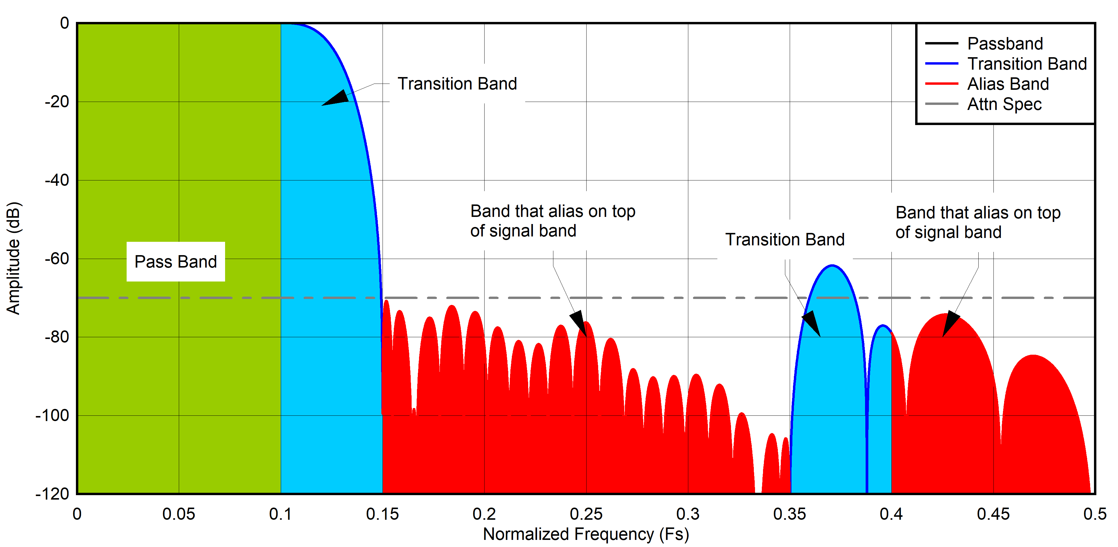 Figure 6-11 Interpretation of the
Decimation Filter Plots
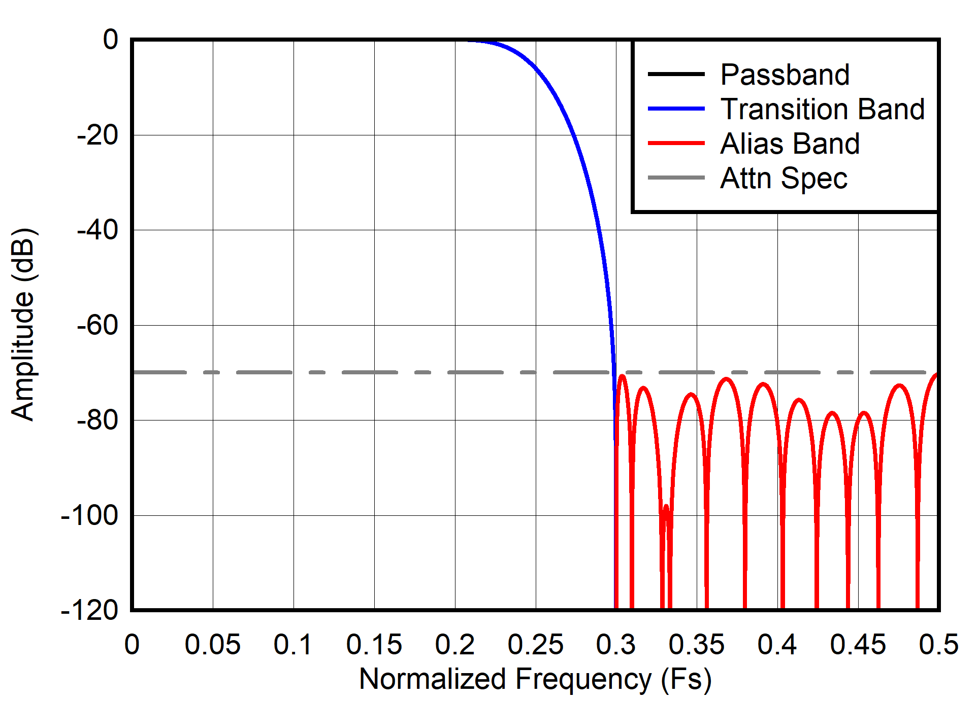 Figure 6-12 Decimation by 2 frequency
response
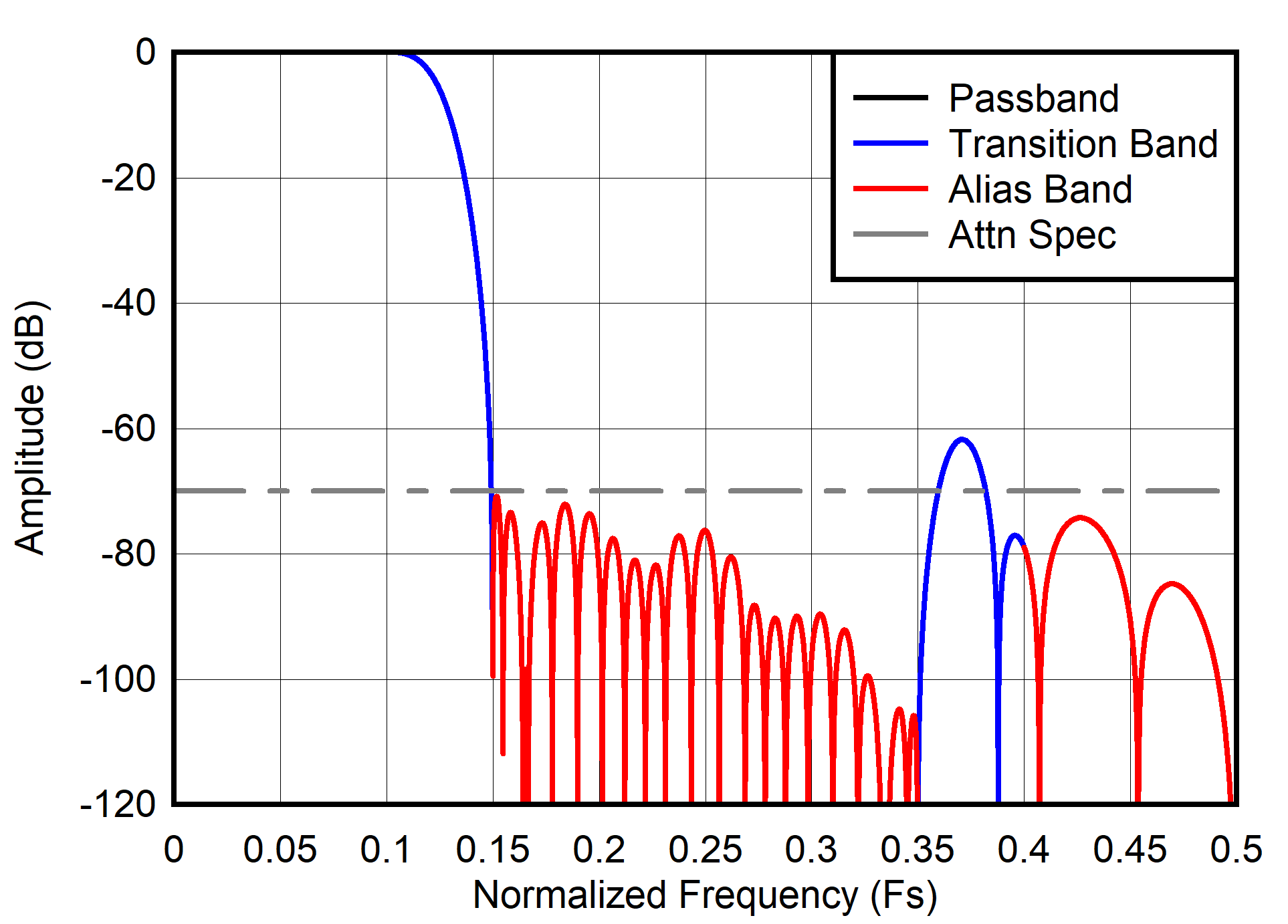 Figure 6-14 Decimation by 4 frequency
response
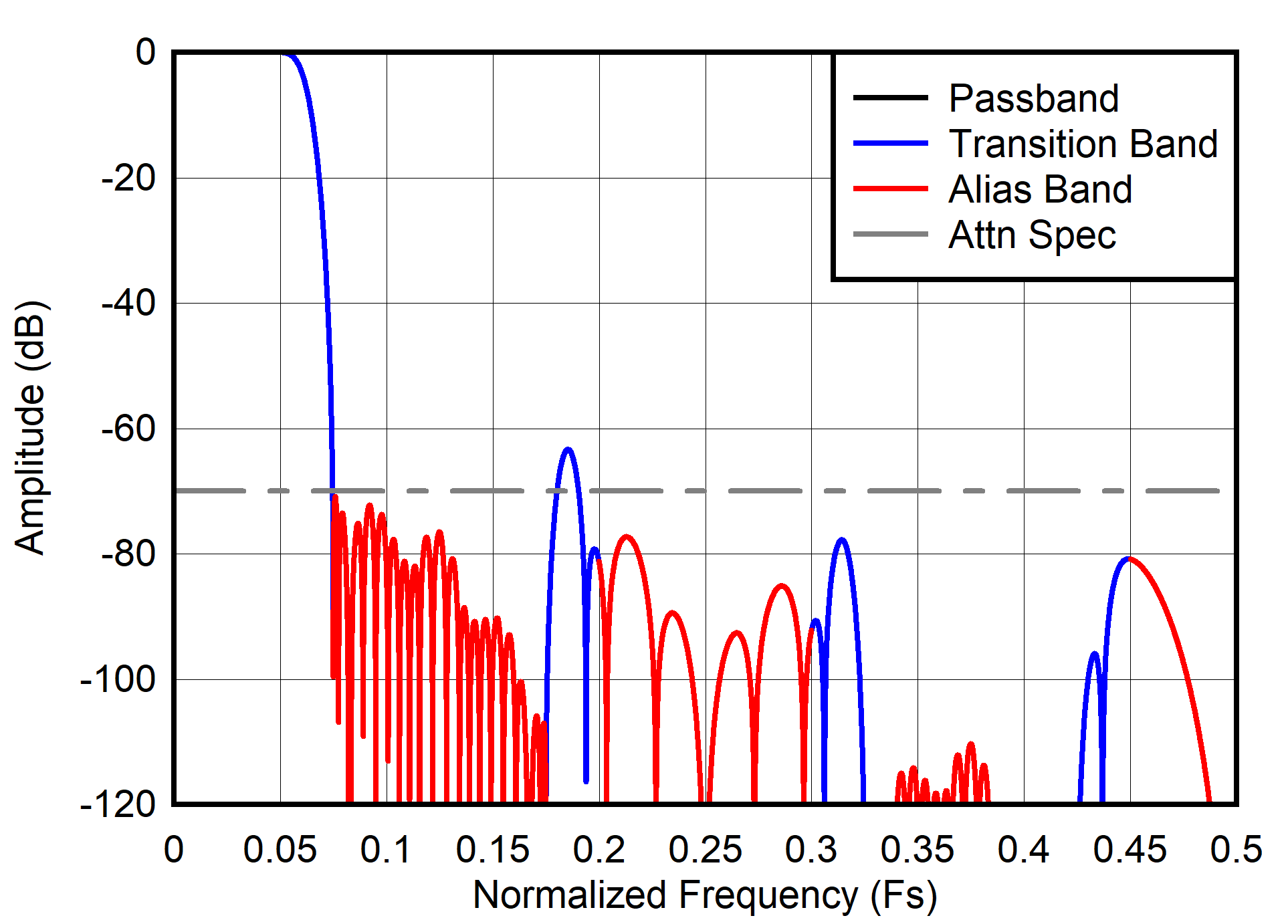 Figure 6-16 Decimation by 8 frequency
response
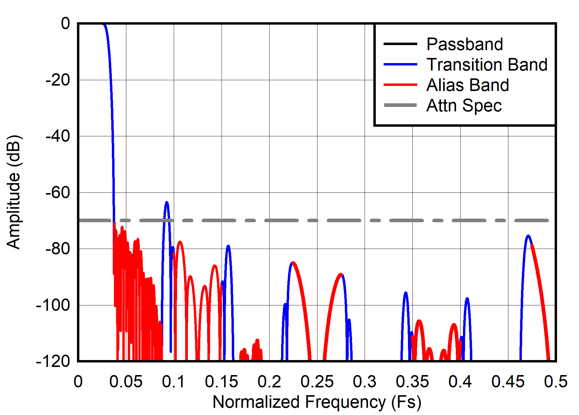 Figure 6-18 Decimation by 16 frequency
response
| FIN = 1 MHz, AIN = -1dBFS, 16-bit resolution mode |
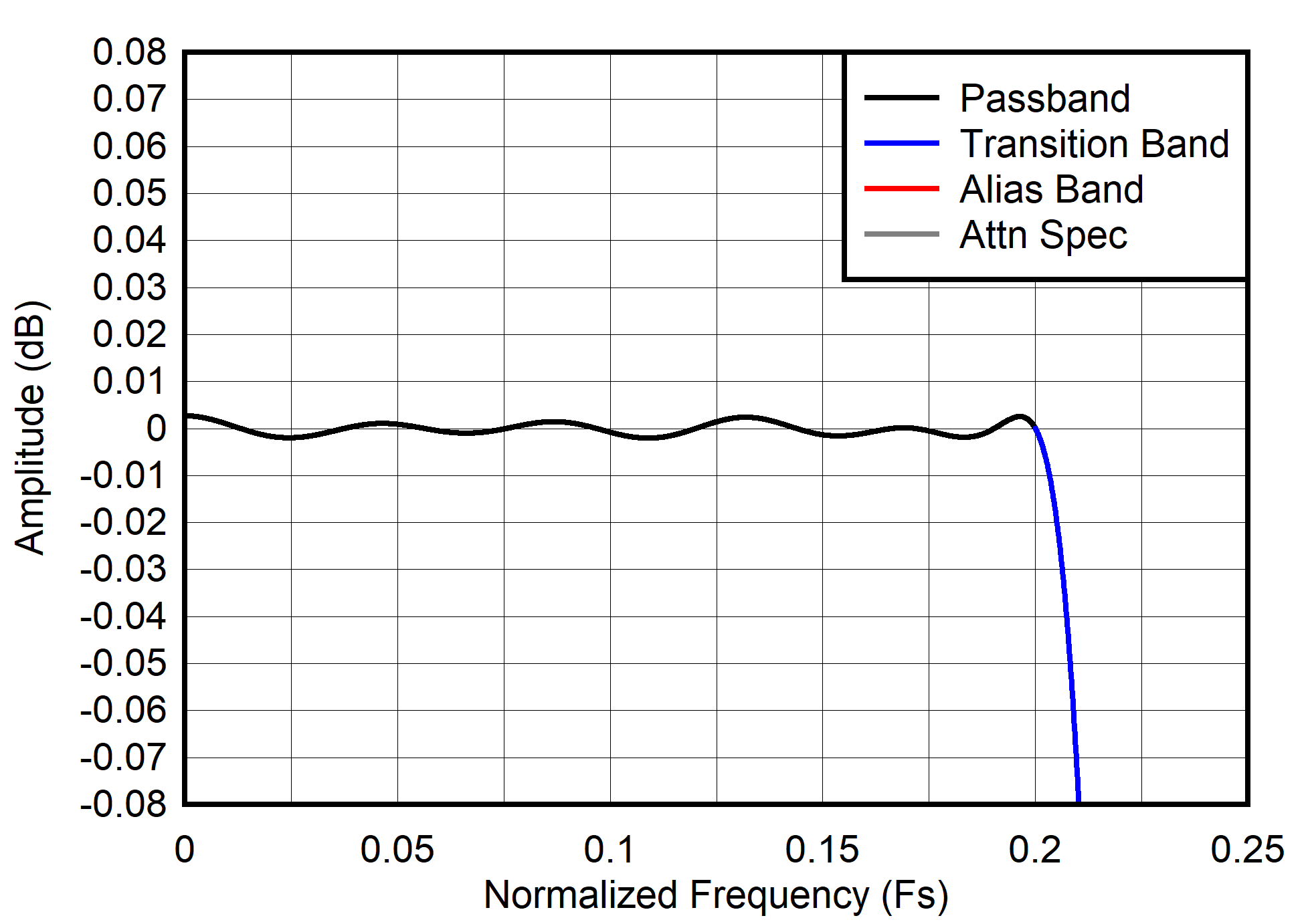 Figure 6-13 Decimation by 2 passband
ripple response
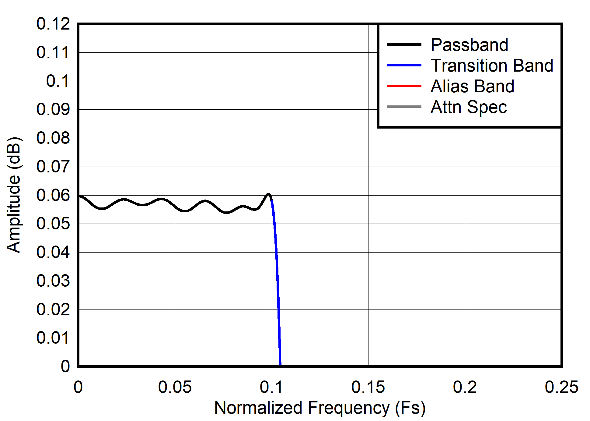 Figure 6-15 Decimation by 4 passband
ripple response
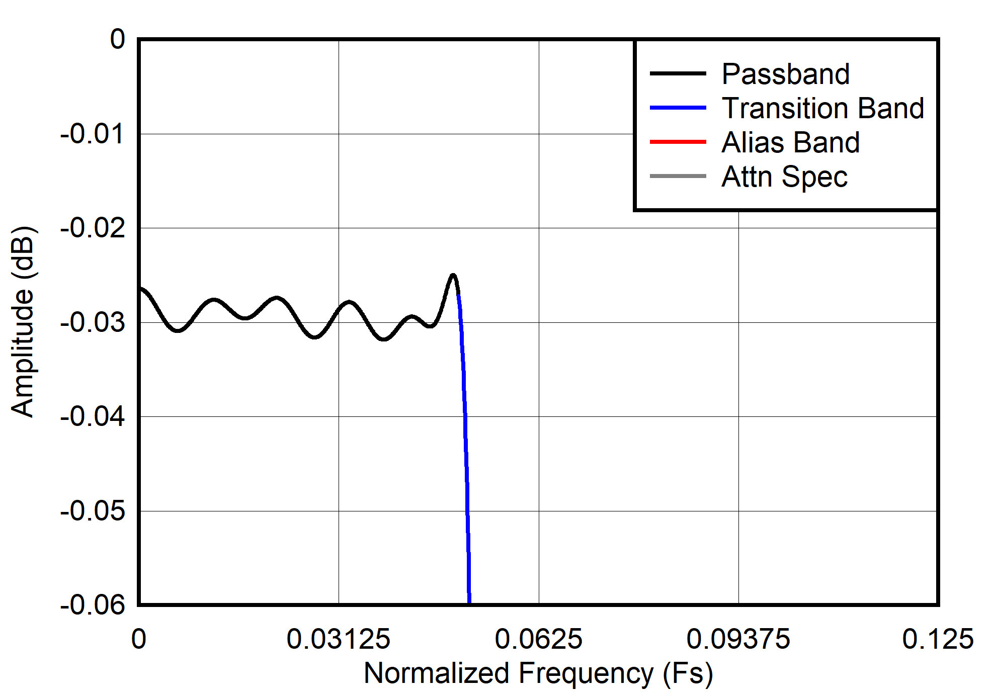 Figure 6-17 Decimation by 8 passband
ripple response
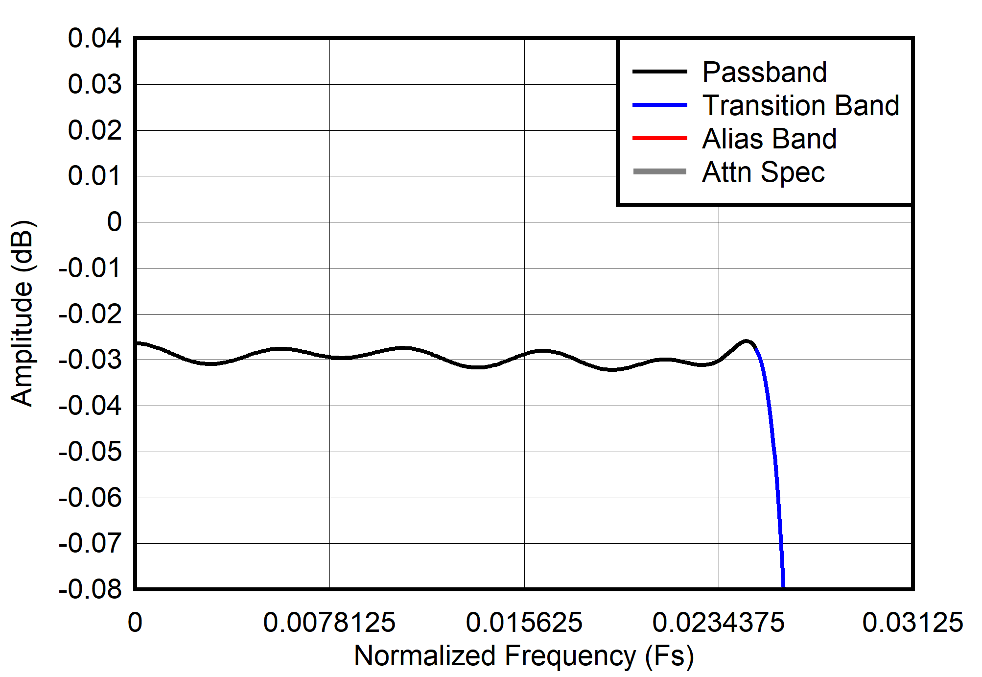 Figure 6-19 Decimation by 16 passband
ripple response
Figure 6-19 Decimation by 16 passband
ripple response6.3.6.1.3 DDC Over-range
The ADC3910Dx and ADC3910Sx has an overrange indicator that can be enabled via SPI write to register 0x205-0x206 to protect the analog inputs from being saturated for extended period of time since latency is increased with decimation. When the alert pin is asserted, it stays high for one clock cycle of FOUT (FS divided by decimation factor) and then de-asserted.
6.3.6.1.4 Output Formatting with Decimation
In serial CMOS mode, the ADC3910Dx and ADC3910Sx has a configurable output data mapping. Default bit size in serial CMOS is 10 bits wide and interface default is set to DDR. Interface options are double data rate (DDR), half double data rate (HDDR), and single data rate (SDR) via SPI write to register 0x098.
By default DDR mode clocks output data by alternating channel A data on the rising and channel B data on the falling edge of DCLK on the same lane. This behavior can be changed to clock all of channel A data first and then channel B data via SPI write to DDR_MODE (0x0A6). HDDR mode clocks channel A data on separate output lanes from channel B data via SPI write to HDDR_EN (0x098).
SDR mode clocks data only on rising edge; therefore, to clock both data samples in a cycle, requires double the data clock speed. The following diagrams show the different available configurations that can be programmed, and Table 6-4 shows actual data and clock rates.
| Output Resolution | Decimation | Lanes | Serialization | DCLK | DCLK Divider | FCLK |
|---|---|---|---|---|---|---|
| Register 0xA7 | Register 0x200 | Registers 0xAE...B3 | Register 0xA6 | Register 0xA8 | Register 0x88 | |
| 8 bits | Bypass | 8 | 1 | FS | /1 | N/A |
| 10 bits | 10 | 1 | FS | /1 | N/A | |
| 12 bits | 12 | 1 | FS | /1 | N/A | |
| /2 | 12 | 1 | FS / 2 | /2 | N/A | |
| /4 | 12 | 1 | FS / 4 | /4 | N/A | |
| /8 | 12 | 1 | FS / 8 | /8 | N/A | |
| /16 | 12 | 1 | FS /16 | /16 | N/A | |
| 16 bits | /2 | 8 | 2 | FS | /2 | FS / 2 |
| /4 | 8 | 2 | FS / 2 | /4 | FS / 2 | |
| 4 | 4 | FS | FS / 4 | |||
| /8 | 8 | 2 | FS / 4 | /8 | FS / 2 | |
| 4 | 4 | FS / 2 | FS / 4 | |||
| 2 | 8 | FS | FS / 8 | |||
| /16 | 8 | 2 | FS / 8 | /16 | FS / 2 | |
| 4 | 4 | FS / 4 | FS / 4 | |||
| 2 | 8 | FS / 2 | FS / 8 | |||
 Figure 6-21 16 Bit, 8 Lanes, 2x Serialization
 Figure 6-22 16 Bit, 4 Lanes, 4x Serialization
 Figure 6-23 16 Bit, 2 Lanes, 8x Serialization
6.3.6.2 Digital Comparator
The ADC3910Dx and ADC3910Sx has two internal digital comparators. The digital comparator controls the output ALERT pin buffer. ALERT pin can be configured as open-drain or push-pull using the ALERT_OD (0x090) register. Figure 6-24 shows the block diagram for the digital comparator.
 Figure 6-24 Digital Comparator Block Diagram
6.3.6.2.1 Comparator Data Select
Each digital comparator has the capability of selecting either channel with or without decimation data via SPI write (0x201, 0x203).
 Figure 6-25 Comparator multiplexer
6.3.6.2.2 Comparator High and Low Threshold
The digital comparator high-side threshold, low-side threshold and hysteresis (optional) parameters are independently programmed for each digital comparator (COMP_THRESHOLD_HI_CHx, COMP_THRESHOLD_LO_CHx, COMP_HYSTERESIS_CHx) via SPI write to registers 0x0C8-0x0D3.