SBASAY5 June 2024 ADS8681W
PRODUCTION DATA
- 1
- 1 Features
- 2 Applications
- 3 Description
- 4 Pin Configuration and Functions
- 5 Specifications
-
6 Detailed Description
- 6.1 Overview
- 6.2 Functional Block Diagram
- 6.3 Feature Description
- 6.4 Device Functional Modes
- 6.5 Programming
-
7 Register Maps
- 7.1
Device Configuration and Register Maps
- 7.1.1 DEVICE_ID_REG Register (address = 00h)
- 7.1.2 RST_PWRCTL_REG Register (address = 04h)
- 7.1.3 SDI_CTL_REG Register (address = 08h)
- 7.1.4 SDO_CTL_REG Register (address = 0Ch)
- 7.1.5 DATAOUT_CTL_REG Register (address = 10h)
- 7.1.6 RANGE_SEL_REG Register (address = 14h)
- 7.1.7 ALARM_REG Register (address = 20h)
- 7.1.8 ALARM_H_TH_REG Register (address = 24h)
- 7.1.9 ALARM_L_TH_REG Register (address = 28h)
- 7.1
Device Configuration and Register Maps
- 8 Application and Implementation
- 9 Device and Documentation Support
- 10Revision History
- 11Mechanical, Packaging, and Orderable Information
Package Options
Mechanical Data (Package|Pins)
- RUM|16
Thermal pad, mechanical data (Package|Pins)
- RUM|16
Orderable Information
6.5.4.2.1 Legacy, SPI-Compatible (SYS-xy-S) Protocols With a Single SDO-x
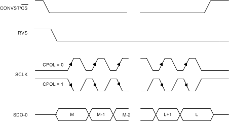
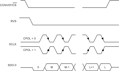
As shown in Table 6-9, the host controller uses any of the four legacy, SPI-compatible protocols to read data from the device. These protocols are SPI-00-S, SPI-01-S, SPI-10-S, or SPI-11-S.
| PROTOCOL | SCLK POLARITY (At CS Falling Edge) | SCLK PHASE (Capture Edge) | MSB BIT LAUNCH EDGE | SDI_CTL_REG | SDO_CTL_REG | DIAGRAM |
|---|---|---|---|---|---|---|
| SPI-00-S | Low | Rising | CS falling | 00h | 00h | Figure 6-28 |
| SPI-01-S | Low | Falling | 1st SCLK rising | 01h | 00h | Figure 6-28 |
| SPI-10-S | High | Falling | CS falling | 02h | 00h | Figure 6-29 |
| SPI-11-S | High | Rising | 1st SCLK falling | 03h | 00h | Figure 6-29 |
On power-up or after coming out of any asynchronous reset, the device supports the SPI-00-S protocol for data read and data write operations. To select a different SPI-compatible protocol for both the data transfer operations:
- Program the SDI_MODE[1:0] bits in the SDI_CTL_REG register. This first write operation adheres to the SPI-00-S protocol. Any subsequent data transfer frames adhere to the newly-selected protocol.
- Set the SDO_MODE[1:0] bits = 00b in the SDO_CTL_REG register.
The SPI transfer protocol selected by configuring the SDI_MODE[1:0] bits in the SDI_CTL_REG register determines the data transfer protocol for both write and read operations. Either data are read from the device or one of the SRC protocols is selected for data read, as explained in the Source-Synchronous (SRC) Protocols section. When data are read from the device, use the selected SPI protocol by configuring the SDO_MODE[1:0] bits = 00b in the SDO_CTL_REG register.
When using any of the SPI-compatible protocols, the RVS output remains low throughout the data transfer frame. See the Timing Requirements table for associated timing parameters.
Figure 6-28 and Figure 6-29 explain the details of the four protocols. The host controller uses a short data transfer frame to read only the required number of MSB bits from the 32-bit output data word. See the Data Transfer Frame section for details
If the host controller uses a long data transfer frame with SDO_CNTL_REG[7:0] = 00h, then the device exhibits daisy-chain operation. See the Multiple Devices: Daisy-Chain Topology section.
 Figure 6-28 Standard SPI Timing Protocol
(CPHA = 0, Single SDO-x)
 Figure 6-29 Standard SPI Timing Protocol
(CPHA = 1, Single SDO-x)