SPRSP74D october 2022 – july 2023 AM2631 , AM2631-Q1 , AM2632 , AM2632-Q1 , AM2634 , AM2634-Q1
PRODUCTION DATA
- 1
- 1 Features
- 2 Applications
- 3 Description
- 4 Revision History
- 5 Device Comparison
-
6 Terminal Configuration and Functions
- 6.1 Pin Diagram
- 6.2 Pin Attributes
- 6.3
Signal Descriptions
- 16
- 6.3.1 ADC
- 6.3.2 ADC_CAL
- 6.3.3 ADC VREF
- 6.3.4 CPSW
- 6.3.5 CPTS
- 6.3.6 DAC
- 6.3.7 Emulation and Debug
- 6.3.8 EPWM
- 6.3.9 EQEP
- 6.3.10 FSI
- 6.3.11 GPIO
- 6.3.12 GPMC
- 6.3.13 I2C
- 6.3.14 LIN
- 6.3.15 MCAN
- 6.3.16 SPI (MCSPI)
- 6.3.17 MMC
- 6.3.18 Power Supply
- 6.3.19 PRU-ICSS
- 6.3.20 QSPI
- 6.3.21 Reserved
- 6.3.22 SDFM
- 6.3.23 System and Miscellaneous
- 6.3.24 UART
- 6.3.25 XBAR
- 6.4 Pin Connectivity Requirements
-
7 Specifications
- 7.1 Absolute Maximum Ratings
- 7.2 Electrostatic Discharge (ESD) Extended Automotive Ratings
- 7.3 Electrostatic Discharge (ESD) Industrial Ratings
- 7.4 Power-On Hours (POH) Summary
- 7.5 Recommended Operating Conditions
- 7.6 Operating Performance Points
- 7.7 Power Consumption Summary
- 7.8 Electrical Characteristics
- 7.9 VPP Specifications for One-Time Programmable (OTP) eFuses
- 7.10 Thermal Resistance Characteristics
- 7.11
Timing and Switching Characteristics
- 7.11.1 Timing Parameters and Information
- 7.11.2 Power Supply Sequencing
- 7.11.3 System Timing
- 7.11.4 Clock Specifications
- 7.11.5
Peripherals
- 7.11.5.1
2-port Gigabit Ethernet MAC (CPSW)
- 7.11.5.1.1 CPSW MDIO Timing
- 7.11.5.1.2
CPSW RMII Timing
- 7.11.5.1.2.1 CPSW RMII Timing Conditions
- 7.11.5.1.2.2 CPSW RMII[x]_REFCLK Timing Requirements - RMII Mode
- 218
- 7.11.5.1.2.3 CPSW RMII[x]_RXD[1:0], RMII[x]_CRS_DV, and RMII[x]_RXER Timing Requirements - RMII Mode
- 220
- 7.11.5.1.2.4 CPSW RMII[x]_TXD[1:0], and RMII[x]_TXEN Switching Characteristics - RMII Mode
- 222
- 7.11.5.1.3
CPSW RGMII Timing
- 7.11.5.1.3.1 CPSW RGMII Timing Conditions
- 7.11.5.1.3.2 CPSW RGMII[x]_RCLK Timing Requirements - RGMII Mode
- 7.11.5.1.3.3 CPSW RGMII[x]_RD[3:0], and RGMII[x]_RCTL Timing Requirements
- 227
- 7.11.5.1.3.4 CPSW RGMII[x]_TCLK Switching Characteristics - RGMII Mode
- 7.11.5.1.3.5 CPSW RGMII[x]_TD[3:0], and RGMII[x]_TCTL Switching Characteristics - RGMII Mode
- 230
- 7.11.5.2 Enhanced Capture (eCAP)
- 7.11.5.3 Enhanced Pulse Width Modulation (ePWM)
- 7.11.5.4 Enhanced Quadrature Encoder Pulse (eQEP)
- 7.11.5.5 Fast Serial Interface (FSI)
- 7.11.5.6 General Purpose Input/Output (GPIO)
- 7.11.5.7
General Purpose Memory Controller (GPMC)
- 7.11.5.7.1 GPMC Timing Conditions
- 7.11.5.7.2 GPMC/NOR Flash Timing Requirements - Synchronous Mode 100MHz
- 7.11.5.7.3 GPMC/NOR Flash Switching Characteristics - Synchronous Mode 100MHz
- 266
- 7.11.5.7.4 GPMC/NOR Flash Timing Requirements - Asynchronous Mode 100MHz
- 7.11.5.7.5 GPMC/NOR Flash Switching Characteristics - Asynchronous Mode 100MHz
- 269
- 7.11.5.7.6 GPMC/NAND Flash Timing Requirements - Asynchronous Mode 100MHz
- 7.11.5.7.7 GPMC/NAND Flash Switching Characteristics - Asynchronous Mode 100MHz
- 272
- 7.11.5.8 Inter-Integrated Circuit (I2C)
- 7.11.5.9 Local Interconnect Network (LIN)
- 7.11.5.10 Modular Controller Area Network (MCAN)
- 7.11.5.11 Serial Peripheral Interface (SPI)
- 7.11.5.12
Multi-Media Card/Secure Digital (MMCSD)
- 7.11.5.12.1 MMC Timing Conditions
- 7.11.5.12.2 MMC Timing Requirements - SD Card Default Speed Mode
- 295
- 7.11.5.12.3 MMC Switching Characteristics - SD Card Default Speed Mode
- 297
- 7.11.5.12.4 MMC Timing Requirements - SD Card High Speed Mode
- 299
- 7.11.5.12.5 MMC Switching Characteristics - SD Card High Speed Mode
- 301
- 7.11.5.13 Quad Serial Peripheral Interface (QSPI)
- 7.11.5.14
Programmable Real-Time Unit and Industrial Communication Subsystem (PRU-ICSS)
- 7.11.5.14.1
PRU-ICSS Programmable Real-Time Unit (PRU)
- 7.11.5.14.1.1 PRU-ICSS PRU Timing Conditions
- 7.11.5.14.1.2 PRU-ICSS PRU Switching Characteristics - Direct Output Mode
- 312
- 7.11.5.14.1.3 PRU-ICSS PRU Timing Requirements - Parallel Capture Mode
- 314
- 7.11.5.14.1.4 PRU-ICSS PRU Timing Requirements - Shift In Mode
- 316
- 7.11.5.14.1.5 PRU-ICSS PRU Switching Characteristics - Shift Out Mode
- 318
- 7.11.5.14.2
PRU-ICSS PRU Sigma Delta and Peripheral Interface
- 7.11.5.14.2.1 PRU-ICSS PRU Sigma Delta and Peripheral Interface Timing Conditions
- 7.11.5.14.2.2 PRU-ICSS PRU Timing Requirements - Sigma Delta Mode
- 322
- 7.11.5.14.2.3 PRU-ICSS PRU Timing Requirements - Peripheral Interface Mode
- 324
- 7.11.5.14.2.4 PRU-ICSS PRU Switching Characteristics - Peripheral Interface Mode
- 326
- 7.11.5.14.3 PRU-ICSS Pulse Width Modulation (PWM)
- 7.11.5.14.4 PRU-ICSS Industrial Ethernet Peripheral (IEP)
- 7.11.5.14.5 PRU-ICSS Universal Asynchronous Receiver Transmitter (UART)
- 7.11.5.14.6 PRU-ICSS Enhanced Capture Peripheral (ECAP)
- 7.11.5.14.7
PRU-ICSS MDIO and MII
- 7.11.5.14.7.1 PRU-ICSS MDIO Timing
- 7.11.5.14.7.2
PRU-ICSS MII Timing
- 7.11.5.14.7.2.1 PRU-ICSS MII Timing Conditions
- 7.11.5.14.7.2.2 PRU-ICSS MII Timing Requirements - MII[x]_RX_CLK
- 359
- 7.11.5.14.7.2.3 PRU-ICSS MII Timing Requirements - MII[x]_RXD[3:0], MII[x]_RX_DV, and MII[x]_RX_ER
- 361
- 7.11.5.14.7.2.4 PRU-ICSS MII Switching Characteristics - MII[x]_TX_CLK
- 363
- 7.11.5.14.7.2.5 PRU-ICSS MII Switching Characteristics - MII[x]_TXD[3:0] and MII[x]_TXEN
- 365
- 7.11.5.14.1
PRU-ICSS Programmable Real-Time Unit (PRU)
- 7.11.5.15 Sigma Delta Filter Module (SDFM)
- 7.11.5.16 Universal Asynchronous Receiver/Transmitter (UART)
- 7.11.5.1
2-port Gigabit Ethernet MAC (CPSW)
- 7.11.6 Emulation and Debug
- 7.12 Decoupling Capacitor Requirements
- 8 Detailed Description
- 9 Applications, Implementation, and Layout
- 10Device and Documentation Support
- 11Mechanical, Packaging, and Orderable Information
Package Options
Refer to the PDF data sheet for device specific package drawings
Mechanical Data (Package|Pins)
- ZCZ|324
Thermal pad, mechanical data (Package|Pins)
Orderable Information

A. In GPMC_CSn[i], i is
equal to 0, 1, 2 or 3.
Figure 7-36 GPMC and NAND Flash — Command
Latch Cycle
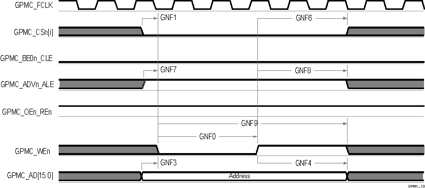
A. In GPMC_CSn[i], i is
equal to 0, 1, 2 or 3.
Figure 7-37 GPMC and NAND Flash — Address
Latch Cycle
A. GNF12 parameter
illustrates amount of time required to internally
sample input data. It is expressed in number of
GPMC functional clock cycles. From start of read
cycle and after GNF12 functional clock cycles,
input data will be internally sampled by active
functional clock edge. GNF12 value must be stored
inside AccessTime register bits field.
B. GPMC_FCLK is an
internal clock (GPMC functional clock) not
provided externally.
C. In GPMC_CSn[i], i is equal to 0, 1, 2 or 3. In
GPMC_WAIT[j], j is equal to 0 or 1.
Figure 7-38 GPMC and NAND Flash — Data
Read Cycle 
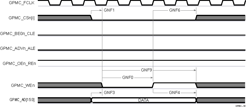
A. In GPMC_CSn[i], i is equal to 0, 1, 2 or 3.
Figure 7-39 GPMC and NAND Flash — Data
Write Cycle