SBAS799 February 2017 AMC1304L05-Q1 , AMC1304L25-Q1 , AMC1304M05-Q1 , AMC1304M25-Q1
PRODUCTION DATA.
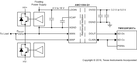
The AMC1304-Q1 is a precision, delta-sigma (ΔΣ) modulator with the output separated from the input circuitry by a capacitive double isolation barrier that is highly resistant to magnetic interference. This barrier is certified to provide reinforced isolation of up to 7000 VPEAK according to the DIN V VDE V 0884-10, UL1577 and CSA standards. Used in conjunction with isolated power supplies, the device prevents noise currents on a high common-mode voltage line from entering the local system ground and interfering with or damaging low voltage circuitry.
The input of the AMC1304-Q1 is optimized for direct connection to shunt resistors or other low voltage-level signal sources. The unique low input voltage range of the ±50-mV device allows significant reduction of the power dissipation through the shunt while supporting excellent ac and dc performance. By using an appropriate digital filter (that is, as integrated on the TMS320F2807x or TMS320F2837x families) to decimate the bit stream, the device can achieve 16 bits of resolution with a dynamic range of 81 dB (13.2 ENOB) at a data rate of 78 kSPS.
On the high-side, the modulator is supplied by an integrated low-dropout (LDO) regulator that allows an unregulated input voltage between 4 V and 18 V (LDOIN). The isolated digital interface operates from a 3.3-V or 5-V power supply (DVDD).
The AMC1304-Q1 is available in a wide-body SOIC-16 (DW) package.
PART NUMBER | PACKAGE | BODY SIZE (NOM) |
---|---|---|
AMC1304x-Q1 | SOIC (16) | 10.30 mm × 7.50 mm |
DATE | REVISION | NOTES |
---|---|---|
February 2017 | * | Initial release. |
DEVICE | INPUT VOLTAGE RANGE | DIFFERENTIAL INPUT RESISTANCE | DIGITAL OUTPUT INTERFACE |
---|---|---|---|
AMC1304L05-Q1 | ±50 mV | 5 kΩ | LVDS |
AMC1304L25-Q1 | ±250 mV | 25 kΩ | LVDS |
AMC1304M05-Q1 | ±50 mV | 5 kΩ | CMOS |
AMC1304M25-Q1 | ±250 mV | 25 kΩ | CMOS |
PIN | I/O | DESCRIPTION | ||
---|---|---|---|---|
NAME | NO. | |||
AMC1304Lx-Q1 (LVDS) |
AMC1304Mx-Q1 (CMOS) |
|||
AGND | 4 | 4 | — | This pin is internally connected to pin 8 and can be left unconnected or tied to high-side ground |
8 | 8 | — | High-side ground reference | |
AINN | 3 | 3 | I | Inverting analog input |
AINP | 2 | 2 | I | Noninverting analog input |
CLKIN | 13 | 13 | I | Modulator clock input, 5 MHz to 20.1 MHz |
CLKIN_N | 12 | — | I | Inverted modulator clock input |
DGND | 9, 16 | 9, 16 | — | Controller-side ground reference |
DOUT | 11 | 11 | O | Modulator data output |
DOUT_N | 10 | — | O | Inverted modulator data output |
DVDD | 14 | 14 | — | Controller-side power supply, 3.0 V to 5.5 V. See the Power-Supply Recommendations section for decoupling recommendations. |
LDOIN | 6 | 6 | — | Low dropout regulator input, 4 V to 18 V |
NC | 1 | 1 | — | This pin can be connected to VCAP or left unconnected |
5 | 5 | — | This pin can be left unconnected or tied to AGND only | |
— | 10, 12 | — | These pins have no internal connection | |
15 | 15 | — | This pin can be left unconnected or tied to DVDD only | |
VCAP | 7 | 7 | — | LDO output. See the Power-Supply Recommendations section for decoupling recommendations. |
MIN | MAX | UNIT | ||
---|---|---|---|---|
Supply voltage | DVDD to DGND | –0.3 | 6.5 | V |
LDO input voltage | LDOIN to AGND | –0.3 | 26 | V |
Analog input voltage at AINP, AINN | AGND – 6 | 3.7 | V | |
Digital input voltage at CLKIN, CLKIN_N | DGND – 0.3 | DVDD + 0.3 | V | |
Input current to any pin except supply pins | –10 | 10 | mA | |
Junction temperature, TJ | 150 | °C | ||
Storage temperature, Tstg | –65 | 150 | °C |
VALUE | UNIT | |||
---|---|---|---|---|
V(ESD) | Electrostatic discharge | Human body model (HBM), per AEC Q100-002(1) | ±2500 | V |
Charged device model (CDM), per AEC Q100-011 | ±1000 |
MIN | NOM | MAX | UNIT | ||
---|---|---|---|---|---|
LDOIN | LDO input supply voltage (LDOIN pin) | 4.0 | 15.0 | 18.0 | V |
DVDD | Digital (controller-side) supply voltage (DVDD pin) | 3.0 | 3.3 | 5.5 | V |
TA | Operating ambient temperature range | –40 | 125 | °C |
THERMAL METRIC (1) | AMC1304x-Q1 | UNIT | |
---|---|---|---|
DW (SOIC) | |||
16 PINS | |||
RθJA | Junction-to-ambient thermal resistance | 80.2 | °C/W |
RθJC(top) | Junction-to-case (top) thermal resistance | 40.5 | °C/W |
RθJB | Junction-to-board thermal resistance | 45.1 | °C/W |
ψJT | Junction-to-top characterization parameter | 11.9 | °C/W |
ψJB | Junction-to-board characterization parameter | 44.5 | °C/W |
RθJC(bot) | Junction-to-case (bottom) thermal resistance | n/a | °C/W |
PARAMETER | TEST CONDITIONS | VALUE | UNIT | |
---|---|---|---|---|
PD | Maximum power dissipation (both sides) | LDOIN = 18 V, DVDD = 5.5 V | 161 | mW |
PD1 | Maximum power dissipation (high-side supply) | LDOIN = 18 V | 117 | mW |
PD2 | Maximum power dissipation (low-side supply) | DVDD = 5.5 V, LVDS, RLOAD = 100 Ω | 44 | mW |
PARAMETER | TEST CONDITIONS | VALUE | UNIT | |
---|---|---|---|---|
GENERAL | ||||
CLR | Minimum air gap (clearance)(1) | Shortest pin-to-pin distance through air | ≥ 8 | mm |
CPG | Minimum external tracking (creepage)(1) | Shortest pin-to-pin distance across the package surface | ≥ 8 | mm |
DTI | Distance through insulation | Minimum internal gap (internal clearance) of the double insulation (2 × 0.0135 mm) | 0.027 | mm |
CTI | Comparative tracking index | DIN EN 60112 (VDE 0303-11); IEC 60112 | ≥ 600 | V |
Material group | According to IEC 60664-1 | I | ||
Overvoltage category per IEC 60664-1 | Rated mains voltage ≤ 300 VRMS | I-IV | ||
Rated mains voltage ≤ 600 VRMS | I-III | |||
Rated mains voltage ≤ 1000 VRMS | I-II | |||
DIN V VDE V 0884-10 (VDE V 0884-10): 2006-12(2) | ||||
VIORM | Maximum repetitive peak isolation voltage | At ac voltage (bipolar or unipolar) | 1414 | VPK |
VIOWM | Maximum-rated isolation working voltage | At ac voltage (sine wave) | 1000 | VRMS |
At dc voltage | 1500 | VDC | ||
VIOTM | Maximum transient isolation voltage | VTEST = VIOTM, t = 60 s (qualification test) | 7000 | VPK |
VTEST = 1.2 x VIOTM, t = 1 s (100% production test) | 8400 | |||
VIOSM | Maximum surge isolation voltage(3) | Test method per IEC 60065, 1.2/50-μs waveform, VTEST = 1.6 x VIOSM = 10000 VPK (qualification) | 6250 | VPK |
qpd | Apparent charge(4) | Method a, after input/output safety test subgroup 2 / 3, Vini = VIOTM, tini = 60 s, Vpd(m) = 1.2 x VIORM = 1697 VPK, tm = 10 s | ≤ 5 | pC |
Method a, after environmental tests subgroup 1, Vini = VIOTM, tini = 60 s, Vpd(m) = 1.6 x VIORM = 2263 VPK, tm = 10 s | ≤ 5 | pC | ||
Method b1, at routine test (100% production) and preconditioning (type test), Vini = VIOTM, tini = 1 s, Vpd(m) = 1.875 x VIORM = 2652 VPK, tm = 1 s | ≤ 5 | pC | ||
CIO | Barrier capacitance, input to output(5) | VIO = 0.5 VPP at 1 MHz | 1.2 | pF |
RIO | Insulation resistance, input to output(5) | VIO = 500 V at TS = 150°C | > 109 | Ω |
Pollution degree | 2 | |||
Climatic category | 40/125/21 | |||
UL1577 | ||||
VISO | Withstand isolation voltage | VTEST = VISO = 5000 VRMS or 7000 VDC, t = 60 s (qualification test), VTEST = 1.2 x VISO = 6000 VRMS, t = 1 s (100% production test) | 5000 | VRMS |
VDE | UL | ||
---|---|---|---|
Certified according to DIN V VDE V 0884-10 (VDE V 0884-10): 2006-12, DIN EN 60950-1 (VDE 0805 Teil 1): 2014-08, and DIN EN 60095 (VDE 0860): 2005-11 | Recognized under UL1577 component recognition and CSA component acceptance NO 5 programs | ||
Reinforced insulation | Single protection | ||
File number: 40040142 | File number: E181974 |
PARAMETER | TEST CONDITIONS | MIN | TYP | MAX | UNIT | |
---|---|---|---|---|---|---|
IS | Safety input, output, or supply current | θJA = 80.2°C/W, LDOIN = 18 V, TJ = 150°C, TA = 25°C, see Figure 3 |
86.5 | mA | ||
PS | Safety input, output, or total power | θJA = 80.2°C/W, TJ = 150°C, TA = 25°C, see Figure 4 | 1558(1) | mW | ||
TS | Maximum safety temperature | 150 | °C |
The maximum safety temperature is the maximum junction temperature specified for the device. The power dissipation and junction-to-air thermal impedance of the device installed in the application hardware determines the junction temperature. The assumed junction-to-air thermal resistance in the Thermal Information table is that of a device installed on a high-K test board for leaded surface-mount packages. The power is the recommended maximum input voltage times the current. The junction temperature is then the ambient temperature plus the power times the junction-to-air thermal resistance.
PARAMETER | TEST CONDITIONS | MIN | TYP | MAX | UNIT | |
---|---|---|---|---|---|---|
ANALOG INPUTS | ||||||
VClipping | Maximum differential voltage input range (AINP-AINN) |
±62.5 | mV | |||
FSR | Specified linear full-scale range (AINP-AINN) |
–50 | 50 | mV | ||
VCM | Operating common-mode input range | –0.032 | 1.2 | V | ||
CID | Differential input capacitance | 2 | pF | |||
IIB | Input bias current | Inputs shorted to AGND | –97 | –72 | –57 | μA |
RID | Differential input resistance | 5 | kΩ | |||
IIO | Input offset current | ±5 | nA | |||
CMTI | Common-mode transient immunity | 15 | kV/μs | |||
CMRR | Common-mode rejection ratio | fIN = 0 Hz, VCM min ≤ VIN ≤ VCM max |
–98 | dB | ||
fIN from 0.1 Hz to 50 kHz, VCM min ≤ VIN ≤ VCM max |
–85 | |||||
BW | Input bandwidth | 800 | kHz | |||
DC ACCURACY | ||||||
DNL | Differential nonlinearity | Resolution: 16 bits | –0.99 | 0.99 | LSB | |
INL | Integral nonlinearity (1) | Resolution: 16 bits | –5 | ±1.5 | 5 | LSB |
EO | Offset error | Initial, at 25°C | –50 | ±2.5 | 50 | µV |
TCEO | Offset error thermal drift (2) | –1.3 | 1.3 | μV/°C | ||
EG | Gain error | Initial, at 25°C | –0.3% | –0.02% | 0.3% | |
TCEG | Gain error thermal drift (3) | –40 | ±20 | 40 | ppm/°C | |
PSRR | Power-supply rejection ratio | LDOIN from 4 V to 18 V, at dc | –110 | dB | ||
LDOIN from 4 V to 18 V, from 0.1 Hz to 50 kHz | –110 | |||||
AC ACCURACY | ||||||
SNR | Signal-to-noise ratio | fIN = 1 kHz | 76 | 81.5 | dB | |
SINAD | Signal-to-noise + distortion | fIN = 1 kHz | 76 | 81 | dB | |
THD | Total harmonic distortion | fIN = 1 kHz | –90 | –81 | dB | |
SFDR | Spurious-free dynamic range | fIN = 1 kHz | 81 | 90 | dB | |
DIGITAL INPUTS/OUTPUTS | ||||||
External Clock | ||||||
fCLKIN | Input clock frequency | 5 | 20 | 20.1 | MHz | |
DutyCLKIN | Duty cycle | 5 MHz ≤ fCLKIN ≤ 20.1 MHz | 40% | 50% | 60% | |
CMOS Logic Family (AMC1304M05-Q1, CMOS with Schmitt Trigger) | ||||||
IIN | Input current | DGND ≤ VIN ≤ DVDD | –1 | 1 | μA | |
CIN | Input capacitance | 5 | pF | |||
VIH | High-level input voltage | 0.7 × DVDD | DVDD + 0.3 | V | ||
VIL | Low-level input voltage | –0.3 | 0.3 × DVDD | V | ||
CLOAD | Output load capacitance | fCLKIN = 20 MHz | 30 | pF | ||
VOH | High-level output voltage | IOH = –20 µA | DVDD – 0.1 | V | ||
IOH = –4 mA | DVDD – 0.4 | |||||
VOL | Low-level output voltage | IOL = 20 µA | 0.1 | V | ||
IOL = 4 mA | 0.4 | |||||
LVDS Logic Family (AMC1304L05-Q1)(4) | ||||||
VT | Differential output voltage | RLOAD = 100 Ω | 250 | 350 | 450 | mV |
VOC | Common-mode output voltage | 1.125 | 1.23 | 1.375 | V | |
VID | Differential input voltage | 100 | 350 | 600 | mV | |
VIC | Common-mode input voltage | VID = 100 mV | 0.05 | 1.25 | 3.25 | V |
II | Receiver input current | DGND ≤ VIN ≤ 3.3 V | –24 | 0 | 20 | µA |
POWER SUPPLY | ||||||
LDOIN | LDOIN pin input voltage | 4.0 | 15.0 | 18.0 | V | |
VCAP | VCAP pin voltage | 3.45 | V | |||
ILDOIN | LDOIN pin input current | 5.3 | 6.5 | mA | ||
DVDD | Controller-side supply voltage | 3.0 | 3.3 | 5.5 | V | |
IDVDD | Controller-side supply current | LVDS, RLOAD = 100 Ω | 6.1 | 8 | mA | |
CMOS, 3.0 V ≤ DVDD ≤ 3.6 V, CLOAD = 5 pF |
2.7 | 4.0 | ||||
CMOS, 4.5 V ≤ DVDD ≤ 5.5 V, CLOAD = 5 pF |
3.2 | 5.5 |
PARAMETER | TEST CONDITIONS | MIN | TYP | MAX | UNIT | |
---|---|---|---|---|---|---|
ANALOG INPUTS | ||||||
VClipping | Maximum differential voltage input range (AINP-AINN) |
±312.5 | mV | |||
FSR | Specified linear full-scale range (AINP-AINN) |
–250 | 250 | mV | ||
VCM | Operating common-mode input range | –0.16 | 1.2 | V | ||
CID | Differential input capacitance | 1 | pF | |||
IIB | Input bias current | Inputs shorted to AGND | –82 | –60 | –48 | μA |
RID | Differential input resistance | 25 | kΩ | |||
IIO | Input offset current | ±5 | nA | |||
CMTI | Common-mode transient immunity | 15 | kV/μs | |||
CMRR | Common-mode rejection ratio | fIN = 0 Hz, VCM min ≤ VIN ≤ VCM max |
–98 | dB | ||
fIN from 0.1 Hz to 50 kHz, VCM min ≤ VIN ≤ VCM max |
–98 | |||||
BW | Input bandwidth | 1000 | kHz | |||
DC ACCURACY | ||||||
DNL | Differential nonlinearity | Resolution: 16 bits | –0.99 | 0.99 | LSB | |
INL | Integral nonlinearity(1) | Resolution: 16 bits | –4 | ±1.5 | 4 | LSB |
EO | Offset error | Initial, at 25°C | –100 | ±25 | 100 | µV |
TCEO | Offset error thermal drift(2) | –1.3 | 1.3 | μV/°C | ||
EG | Gain error | Initial, at 25°C | –0.2% | –0.05% | 0.2% | |
TCEG | Gain error thermal drift(3) | –40 | ±20 | 40 | ppm/°C | |
PSRR | Power-supply rejection ratio | LDOIN from 4 V to 18 V, at dc | –110 | dB | ||
LDOIN from 4 V to 18 V, from 0.1 Hz to 50 kHz |
–110 | |||||
AC ACCURACY | ||||||
SNR | Signal-to-noise ratio | fIN = 1 kHz | 82 | 85 | dB | |
SINAD | Signal-to-noise + distortion | fIN = 1 kHz | 80 | 84 | dB | |
THD | Total harmonic distortion | fIN = 1 kHz | –90 | –81 | dB | |
SFDR | Spurious-free dynamic range | fIN = 1 kHz | 81 | 90 | dB | |
DIGITAL INPUTS/OUTPUTS | ||||||
External Clock | ||||||
fCLKIN | Input clock frequency | 5 | 20 | 20.1 | MHz | |
DutyCLKIN | Duty cycle | 5 MHz ≤ fCLKIN ≤ 20.1 MHz | 40% | 50% | 60% | |
CMOS Logic Family (AMC1304M25-Q1, CMOS with Schmitt Trigger) | ||||||
IIN | Input current | DGND ≤ VIN ≤ DVDD | –1 | 1 | μA | |
CIN | Input capacitance | 5 | pF | |||
VIH | High-level input voltage | 0.7 × DVDD | DVDD + 0.3 | V | ||
VIL | Low-level input voltage | –0.3 | 0.3 × DVDD | V | ||
CLOAD | Output load capacitance | fCLKIN = 20 MHz | 30 | pF | ||
VOH | High-level output voltage | IOH = –20 µA | DVDD – 0.1 | V | ||
IOH = –4 mA | DVDD – 0.4 | V | ||||
VOL | Low-level output voltage | IOL = 20 µA | 0.1 | V | ||
IOL = 4 mA | 0.4 | V | ||||
LVDS Logic Family (AMC1304L25-Q1)(4) | ||||||
VT | Differential output voltage | RLOAD = 100 Ω | 250 | 350 | 450 | mV |
VOC | Common-mode output voltage | 1.125 | 1.23 | 1.375 | V | |
VID | Differential input voltage | 100 | 350 | 600 | mV | |
VIC | Common-mode input voltage | VID = 100 mV | 0.05 | 1.25 | 3.25 | V |
II | Receiver input current | DGND ≤ VIN ≤ 3.3 V | –24 | 0 | 20 | µA |
POWER SUPPLY | ||||||
LDOIN | LDOIN pin input voltage | 4.0 | 15.0 | 18.0 | V | |
VCAP | VCAP pin voltage | 3.45 | V | |||
ILDOIN | LDOIN pin input current | 5.3 | 6.5 | mA | ||
DVDD | Controller-side supply voltage | 3.0 | 3.3 | 5.5 | V | |
IDVDD | Controller-side supply current | LVDS, RLOAD = 100 Ω | 6.1 | 8.0 | mA | |
CMOS, 3.0 V ≤ DVDD ≤ 3.6 V, CLOAD = 5 pF |
2.7 | 4.0 | ||||
CMOS, 4.5 V ≤ DVDD ≤ 5.5 V, CLOAD = 5 pF |
3.2 | 5.5 |
PARAMETER | TEST CONDITIONS | MIN | TYP | MAX | UNIT | |
---|---|---|---|---|---|---|
tCLK | CLKIN, CLKIN_N clock period | 49.75 | 50 | 200 | ns | |
tHIGH | CLKIN, CLKIN_N clock high time | 19.9 | 25 | 120 | ns | |
tLOW | CLKIN, CLKIN_N clock low time | 19.9 | 25 | 120 | ns | |
tD | Falling edge of CLKIN, CLKIN_N to DOUT, DOUT_N valid delay | 0 | 15 | ns | ||
tISTART | Interface startup time | DVDD at 3.0 V (min) to DOUT, DOUT_N valid with LDO_IN > 4 V | 32 | 32 | CLKIN cycles | |
tASTART | Analog startup time | LDOIN step to 4 V with DVDD ≥ 3.0 V, and 0.1 µF at VCAP pin | 1 | ms |
LDOIN = 18 V (worst case) |
TA up to 150°C, stress voltage frequency = 60 Hz |
AMC1304x25-Q1 |
AMC1304x25-Q1 |
AMC1304x05-Q1 |
AMC1304x05-Q1 |
AMC1304x05-Q1 |
AMC1304x05-Q1, 4096-point FFT, VIN = 100 mVPP |
AMC1304x25-Q1, 4096-point FFT, VIN = 500 mVPP |
AMC1304x05-Q1 |
AMC1304x05-Q1 |
AMC1304x25-Q1 |
AMC1304x25-Q1 |
AMC1304x25-Q1 |
AMC1304x05-Q1, 4096-point FFT, VIN = 100 mVPP |
AMC1304x25-Q1, 4096-point FFT, VIN = 500 mVPP |
The differential analog input (AINP and AINN) of the AMC1304-Q1 is a fully-differential amplifier feeding the switched-capacitor input of a second-order, delta-sigma (ΔΣ) modulator stage that digitizes the input signal into a 1-bit output stream. The isolated data output (DOUT and DOUT_N) of the converter provides a stream of digital ones and zeros that is synchronous to the externally-provided clock source at the CLKIN pin with a frequency in the range of 5 MHz to 20.1 MHz. The time average of this serial bit-stream output is proportional to the analog input voltage.
The Functional Block Diagram section shows a detailed block diagram of the AMC1304-Q1. The analog input range is tailored to directly accommodate a voltage drop across a shunt resistor used for current sensing. The SiO2-based capacitive isolation barrier supports a high level of magnetic field immunity as described in the ISO72x Digital Isolator Magnetic-Field Immunity application report (SLLA181A), available for download at www.ti.com. The external clock input simplifies the synchronization of multiple current-sensing channels on the system level. The extended frequency range of up to 20 MHz supports higher performance levels compared to the other solutions available on the market.
The AMC1304-Q1 incorporates a front-end circuitry that contains a differential amplifier and sampling stage, followed by a ΔΣ modulator. The gain of the differential amplifier is set by internal precision resistors to a factor of 4 for devices with a specified input voltage range of ±250 mV (this value is for the AMC1304x25-Q1), or to a factor of 20 in devices with a ±50-mV input voltage range (for the AMC1304x05-Q1), resulting in a differential input impedance of 5 kΩ (for the AMC1304x05-Q1) or 25 kΩ (for the AMC1304x25-Q1).
Consider the input impedance of the AMC1304-Q1 in designs with high-impedance signal sources that can cause degradation of gain and offset specifications. The importance of this effect, however, depends on the desired system performance. Additionally, the input bias current caused by the internal common-mode voltage at the output of the differential amplifier causes an offset that is dependent on the actual amplitude of the input signal. See the Isolated Voltage Sensing section for more details on reducing these effects.
There are two restrictions on the analog input signals (AINP and AINN). First, if the input voltage exceeds the range AGND – 6 V to 3.7 V, the input current must be limited to 10 mA because the device input electrostatic discharge (ESD) diodes turn on. In addition, the linearity and noise performance of the device are ensured only when the differential analog input voltage remains within the specified linear full-scale range (FSR), that is ±250 mV (for the AMC1304x25-Q1) or ±50 mV (for the AMC1304x05-Q1), and within the specified input common-mode range.
The modulator implemented in the AMC1304-Q1 is a second-order, switched-capacitor, feed-forward ΔΣ modulator, such as the one conceptualized in Figure 48. The analog input voltage VIN and the output V5 of the 1-bit digital-to-analog converter (DAC) are differentiated, providing an analog voltage V1 at the input of the first integrator stage. The output of the first integrator feeds the input of the second integrator stage, resulting in output voltage V3 that is differentiated with the input signal VIN and the output of the first integrator V2. Depending on the polarity of the resulting voltage V4, the output of the comparator is changed. In this case, the 1-bit DAC responds on the next clock pulse by changing its analog output voltage V5, causing the integrators to progress in the opposite direction and forcing the value of the integrator output to track the average value of the input.
The modulator shifts the quantization noise to high frequencies, as shown in Figure 49. Therefore, use a low-pass digital filter at the output of the device to increase the overall performance. This filter is also used to convert from the 1-bit data stream at a high sampling rate into a higher-bit data word at a lower rate (decimation). TI's microcontroller families TMS320F2807x and TMS320F2837x offer a suitable programmable, hardwired filter structure termed a sigma-delta filter module (SDFM) optimized for usage with the AMC1304-Q1 family. Alternatively, a field-programmable gate array (FPGA) can be used to implement the digital filter.
A differential input signal of 0 V ideally produces a stream of ones and zeros that are high 50% of the time. A differential input of 250 mV (for the AMC1304x25-Q1) or 50 mV (for the AMC1304x05-Q1) produces a stream of ones and zeros that are high 90% of the time. A differential input of –250 mV (–50 mV for the AMC1304x05-Q1) produces a stream of ones and zeros that are high 10% of the time. These input voltages are also the specified linear ranges of the different AMC1304-Q1 versions with performance as specified in this data sheet. If the input voltage value exceeds these ranges, the output of the modulator shows non-linear behavior when the quantization noise increases. The output of the modulator clips with a stream of only zeros with an input less than or equal to –312.5 mV (–62.5 mV for the AMC1304x05-Q1) or with a stream of only ones with an input greater than or equal to 312.5 mV (62.5 mV for the AMC1304x05-Q1). In this case, however, the AMC1304-Q1 generates a single 1 (if the input is at negative full-scale) or 0 every 128 clock cycles to indicate proper device function (see the Fail-Safe Output section for more details). The input voltage versus the output modulator signal is shown in Figure 50.
The density of ones in the output bit-stream for any input voltage value (with the exception of a full-scale input signal, as described in the Output Behavior in Case of a Full-Scale Input section) can be calculated using Equation 1:
The AMC1304-Q1 system clock is typically 20 MHz and is provided externally at the CLKIN pin. Data are synchronously provided at 20 MHz at the DOUT pin. Data change at the CLKIN falling edge. For more details, see the Switching Characteristics table.
In the case of a missing high-side supply voltage (LDOIN), the output of a ΔΣ modulator is not defined and can cause a system malfunction. In systems with high safety requirements, this behavior is not acceptable. Therefore, the AMC1304-Q1 implements a fail-safe output function that ensures the device maintains its output level in case of a missing LDOIN, as shown in Figure 51.
If a full-scale input signal is applied to the AMC1304-Q1 (that is, VIN ≥ VClipping), the device generates a single one or zero every 128 bits at DOUT, depending on the actual polarity of the signal being sensed, as shown in Figure 52. In this way, differentiating between a missing LDOIN and a full-scale input signal is possible on the system level.
NOTE
Information in the following applications sections is not part of the TI component specification, and TI does not warrant its accuracy or completeness. TI’s customers are responsible for determining suitability of components for their purposes. Customers should validate and test their design implementation to confirm system functionality.
The modulator generates a bit stream that is processed by a digital filter to obtain a digital word similar to a conversion result of a conventional analog-to-digital converter (ADC). A very simple filter, built with minimal effort and hardware, is a sinc3-type filter, as shown in Equation 2:
This filter provides the best output performance at the lowest hardware size (count of digital gates) for a second-order modulator. All the characterization in this document is also done with a sinc3 filter with an oversampling ratio (OSR) of 256 and an output word duration of 16 bits.
The effective number of bits (ENOB) is often used to compare the performance of ADCs and ΔΣ modulators. Figure 53 shows the ENOB of the AMC1304-Q1 with different oversampling ratios. In this document, this number is calculated from the SNR by using Equation 3:
An example code for implementing a sinc3 filter in an FPGA is discussed in the Combining ADS1202 with FPGA Digital Filter for Current Measurement in Motor Control Applications application note (SBAA094), available for download at www.ti.com.
Isolated ΔΣ modulators are being widely used in new-generation traction inverter designs because of their high ac and dc performance. Traction inverters are critical parts of electrical and hybrid electrical vehicles. The input structure of the AMC1304-Q1 is optimized for use with low-impedance shunt resistors and is therefore tailored for isolated current sensing using shunts.
A typical operation of the device in a traction inverter application is shown in Figure 54. When the inverter stage is part of a motor drive system, measurement of the motor phase current is done via the shunt resistors (RSHUNT). Depending on the system design, either all three or only two phase currents are sensed.
In this example, an additional fourth AMC1304-Q1 is used to support isolated voltage sensing of the dc link. This high voltage is reduced using a high-impedance resistive divider before being sensed by the device across a smaller resistor. The value of this resistor can degrade the performance of the measurement, as described in the Isolated Voltage Sensing section.
The typically recommended RC filter in front of a ΔΣ modulator to improve signal-to-noise performance of the signal path is not required for the AMC1304-Q1. By design, the input bandwidth of the analog front-end of the device is limited to 1 MHz.
For modulator output bit-stream filtering, a device from TI's TMS320F2807x family of low-cost microcontrollers (MCUs) or TMS320F2837x family of dual-core MCUs is recommended. These families support up to eight channels of dedicated hardwired filter structures that significantly simplify system level design by offering two filtering paths per channel: one providing high accuracy results for the control loop and one fast response path for overcurrent detection.
In motor control applications, a very fast response time for overcurrent detection is required. The time for fully settling the filter in case of a step-signal at the input of the modulator depends on its order; that is, a sinc3 filter requires three data updates for full settling (with fDATA = fCLK / OSR). Therefore, for overcurrent protection, filter types other than sinc3 can be a better choice; an alternative is the sinc2 filter. Figure 55 compares the settling times of different filter orders.
The delay time of the sinc filter with a continuous signal is half of its settling time.
The AMC1304-Q1 is optimized for usage in current-sensing applications using low-impedance shunts. However, the device can also be used in isolated voltage-sensing applications if the affect of the (usually higher) impedance of the resistor used in this case is considered.
Figure 56 shows a simplified circuit typically used in high-voltage-sensing applications. The high impedance resistors (R1 and R2) are used as voltage dividers and dominate the current value definition. The resistance of the sensing resistor R3 is chosen to meet the input voltage range of the AMC1304-Q1. This resistor and the differential input impedance of the device (the AMC1304x25-Q1 is 25 kΩ, the AMC1304x05-Q1 is 5 kΩ) also create a voltage divider that results in an additional gain error. With the assumption of R1, R2, and RIN having a considerably higher value than R3, the resulting total gain error can be estimated using Equation 4, with EG being the gain error of the AMC1304-Q1.
This gain error can be easily minimized during the initial system-level gain calibration procedure.
As indicated in Figure 56, the output of the integrated differential amplifier is internally biased to a common-mode voltage of 2 V. This voltage results in a bias current IIB through the resistive network R4 and R5 (or R4' and R5') used for setting the gain of the amplifier. The value range of this current is specified in the Electrical Characteristics table. This bias current generates additional offset error that depends on the value of the resistor R3. Because the value of this bias current depends on the actual common-mode amplitude of the input signal (as illustrated in Figure 57), the initial system offset calibration does not minimize its effect. Therefore, in systems with high accuracy requirements, TI recommends using a series resistor at the negative input (AINN) of the AMC1304-Q1 with a value equal to the shunt resistor R3 (that is, R3' = R3 in Figure 56) to eliminate the affect of the bias current.
This additional series resistor (R3') influences the gain error of the circuit. The effect can be calculated using Equation 5 with R5 = R5' = 50 kΩ and R4 = R4' = 2.5 kΩ (for the AMC1304x05-Q1) or 12.5 kΩ (for the AMC1304x25-Q1).
Figure 57 shows the dependency of the input bias current on the common-mode voltage at the input of the AMC1304-Q1.
Do not leave the inputs of the AMC1304-Q1 unconnected (floating) when the device is powered up. If both modulator inputs are left floating, the input bias current drives them to the output common-mode of the analog front end of approximately 2 V that is above the specified input common-mode range. As a result, the front gain diminishes and the modulator outputs a bitstream resembling a zero input differential voltage.