SLPS667B February 2017 – June 2024 CSD17318Q2
PRODUCTION DATA
- 1
- 1Features
- 2Applications
- 3Description
- 4Specifications
- 5Device and Documentation Support
- 6Revision History
- 7Mechanical, Packaging, and Orderable Information
Package Options
Refer to the PDF data sheet for device specific package drawings
Mechanical Data (Package|Pins)
- DQK|6
Thermal pad, mechanical data (Package|Pins)
Orderable Information
4.2 Thermal Characteristics
TA = 25°C (unless otherwise noted)
| PARAMETER | MIN | TYP | MAX | UNIT | |
|---|---|---|---|---|---|
| RθJC | Thermal resistance junction-to-case(1) | 7.9 | °C/W | ||
| RθJA | Thermal resistance junction-to-ambient(1)(2) | 65 | °C/W | ||
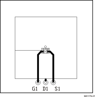
(1) RθJC is determined with the device mounted on a 1in2
(6.45cm2), 2oz (0.071mm) thick Cu pad on a 1.5in × 1.5in (3.81cm
× 3.81cm), 0.06in (1.52mm) thick FR4 PCB. RθJC is specified by
design, whereas RθJA is determined by the user’s board design.
(2) Device mounted on FR4 material with 1in2 (6.45cm2), 2oz
(0.071mm) thick Cu.

|
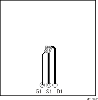
Max RθJA = 65°C/W when mounted on 1in2 (6.45cm2) of 2oz (0.071mm) thick Cu. |

|
Max RθJA = 250°C/W when mounted on a minimum pad area of 2oz (0.071mm) thick Cu. |