DLPS029F April 2013 – May 2019 DLPC350
PRODUCTION DATA.
- 1 Features
- 2 Applications
- 3 Description
- 4 Revision History
- 5 Pin Configuration and Functions
-
6 Specifications
- 6.1 Absolute Maximum Ratings
- 6.2 ESD Ratings
- 6.3 Recommended Operating Conditions
- 6.4 Thermal Information
- 6.5 I/O Electrical Characteristics
- 6.6 I2C0 and I2C1 Interface Timing Requirements
- 6.7 Port 1 Input Pixel Interface Timing Requirements
- 6.8 Port 2 Input Pixel Interface (FPD-Link Compatible LVDS Input) Timing Requirements
- 6.9 System Oscillator Timing Requirements
- 6.10 Reset Timing Requirements
- 6.11 Video Timing Input Blanking Specification
- 6.12 Programmable Output Clocks Switching Characteristics
- 6.13 DMD Interface Switching Characteristics
- 6.14 JTAG Interface: I/O Boundary Scan Application Switching Characteristics
- 7 Parameter Measurement Information
- 8 Detailed Description
- 9 Application and Implementation
- 10Power Supply Recommendations
-
11Layout
- 11.1 Layout Guidelines
- 11.2 Layout Example
- 12Device and Documentation Support
- 13Mechanical, Packaging, and Orderable Information
Package Options
Mechanical Data (Package|Pins)
- ZFF|419
Thermal pad, mechanical data (Package|Pins)
11.1.2 DMD Termination Requirements
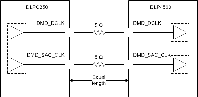
Table 17 lists the termination requirements for the DMD interface. These series resistors should be placed as close to the DLPC350 pins as possible while following all PCB guidelines.
Table 17. Termination Requirements for DMD Interface
| SIGNALS | SYSTEM TERMINATION |
|---|---|
| DMD_D(23:0), DMD_TRC, DMD_SCTRL, DMD_LOADB, DMD_DRC_STRB, DMD_DRC_BUS, DMD_SAC_CLK, and DMD_SAC_BUS | External 5-Ω series termination at the transmitter |
| DMD_DCLK | External 5-Ω series termination at the transmitter |
| DMD_DRC_OE | External 0-Ω series termination. This signal must be externally pulled-up to VDD_DMD via a 30-kΩ to 51-kΩ resistor |
DMD_CLK and DMD_SAC_CLK clocks should be equal lengths, as shown in Figure 24.
 Figure 24. Series-Terminated Clocks