DLPS024G August 2012 – February 2020 DLPC410
PRODUCTION DATA.
- 1 Features
- 2 Applications
- 3 Description
- 4 Revision History
- 5 Description (continued)
- 6 Pin Configuration and Functions
- 7 Specifications
-
8 Detailed Description
- 8.1 Overview
- 8.2 Functional Block Diagrams
- 8.3
Feature Description
- 8.3.1
DLPC410 Binary Pattern Data Path
- 8.3.1.1 DIN_A, DIN_B, DIN_C, DIN_D Input Data Buses
- 8.3.1.2 DCLKIN Input Clocks
- 8.3.1.3 DVALID Input Signals
- 8.3.1.4 DOUT_A, DOUT_B, DOUT_C, DOUT_D Output Data Buses
- 8.3.1.5 DCLKOUT Output Clocks
- 8.3.1.6 SCTRL Output Signals
- 8.3.1.7 Supported DMD Bus Sizes
- 8.3.1.8 Row Cycle definition
- 8.3.1.9 DLP9500 and DLP9500UV Input Data Formatting
- 8.3.1.10 DLP7000 and DLP7000UV Input Data Bus
- 8.3.1.11 DLP650LNIR Input Data Bus
- 8.3.2 Data Bus Operations
- 8.3.3 DMD Block Operations
- 8.3.4 Other Data Control Inputs
- 8.3.5 Miscellaneous Control Inputs
- 8.3.6 Miscellaneous Status Outputs
- 8.3.1
DLPC410 Binary Pattern Data Path
- 8.4 Device Functional Modes
- 8.5 Programming
- 9 Application and Implementation
- 10Power Supply Recommendations
- 11Layout
- 12Device and Documentation Support
- 13Mechanical, Packaging, and Orderable Information
Package Options
Mechanical Data (Package|Pins)
- DLP|676
Thermal pad, mechanical data (Package|Pins)
Orderable Information
8.3.2.2 Single Row Write Operation
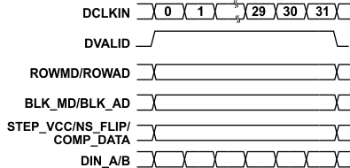
Once initialization is complete (INIT_ACTIVE = 0) the user is free to send data and control information to the DLPC410. When the user asserts the DVALID signal for the LVDS input buses, the DLPC410 samples the customer supplied binary input pattern data (DIN) as well as the Row Mode, Row Address, Block Mode, Block Address, and other control information. The DLPC410 then sends pattern data synchronously to the DMD along with row address and control information. The row cycle period is defined by the Clocks per Row in Table 11 and is synchronous with DVALID as shown in Figure 9. If DVALID is removed midway in a Row Cycle, the DLPC410 continues loading data regardless of data validity until the internal row cycle counter reaches the terminal count of Clocks/Row for that DMD.
Figure 9 is an example of a single Row Cycle for the DLP7000 DMD. A total of 32 bits of input data are presented to the DLPC410 on each clock edge (16 bits on Bus A + 16 bits on Bus B) . An entire line must be written for data to be latched into DMD memory and it requires 16 DDR clock cycles to write a single row of 1024 bits.
 Figure 9. Single Row Write Operation (DLP7000 DMD)