DLPS024G August 2012 – February 2020 DLPC410
PRODUCTION DATA.
- 1 Features
- 2 Applications
- 3 Description
- 4 Revision History
- 5 Description (continued)
- 6 Pin Configuration and Functions
- 7 Specifications
-
8 Detailed Description
- 8.1 Overview
- 8.2 Functional Block Diagrams
- 8.3
Feature Description
- 8.3.1
DLPC410 Binary Pattern Data Path
- 8.3.1.1 DIN_A, DIN_B, DIN_C, DIN_D Input Data Buses
- 8.3.1.2 DCLKIN Input Clocks
- 8.3.1.3 DVALID Input Signals
- 8.3.1.4 DOUT_A, DOUT_B, DOUT_C, DOUT_D Output Data Buses
- 8.3.1.5 DCLKOUT Output Clocks
- 8.3.1.6 SCTRL Output Signals
- 8.3.1.7 Supported DMD Bus Sizes
- 8.3.1.8 Row Cycle definition
- 8.3.1.9 DLP9500 and DLP9500UV Input Data Formatting
- 8.3.1.10 DLP7000 and DLP7000UV Input Data Bus
- 8.3.1.11 DLP650LNIR Input Data Bus
- 8.3.2 Data Bus Operations
- 8.3.3 DMD Block Operations
- 8.3.4 Other Data Control Inputs
- 8.3.5 Miscellaneous Control Inputs
- 8.3.6 Miscellaneous Status Outputs
- 8.3.1
DLPC410 Binary Pattern Data Path
- 8.4 Device Functional Modes
- 8.5 Programming
- 9 Application and Implementation
- 10Power Supply Recommendations
- 11Layout
- 12Device and Documentation Support
- 13Mechanical, Packaging, and Orderable Information
Package Options
Mechanical Data (Package|Pins)
- DLP|676
Thermal pad, mechanical data (Package|Pins)
Orderable Information
9.2 Typical Application
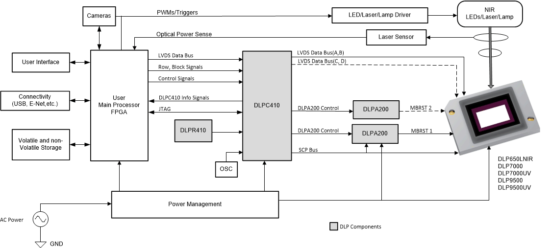
A typical embedded system application using the DLPC410 controller is shown in Figure 21. The DLPC410, the DMD, and their associated DLP components do not specifically determine the application in which the components are used - customer applications and use cases may vary widely, from Digital Image Lithography to 3D Printing to 3D Scanners using Structured Light. The DMD is capable of being used with multiple illumination source types, from Lasers and LEDs to wide band wavelength mercury halide lamps. The DLPC410 supported DMDs cover applications utilizing ultraviolet (UV), visible, and/or near-infrared (NIR) wavelengths. The duration of each binary pattern displayed on the DMD is totally under control of the Applications Processor. The displayed patterns could be strictly binary patterns or could be bit weight exposures of varying durations representing encoded PWM-based gray scales. The timing of the micromirrors and the illumination sources are controlled at the discretion of a Customer Applications Processor and in many solid state cases, provide best performance when source illuminators are synchronous to the commanded DMD micromirror transitions. The speed, diversity, programmability, and flexibility of the DLPC410 building blocks provide an electro-optical cornerstone for customers to build upon to create applications limited only by customer ingenuity.
In Figure 21, the MBRST 2 signals and the C, D LVDS Data buses are shown with dashed lines to indicate that some DMDs do not require these signals to be used. TI's Reference Design and Evaluation Modules leverage a DLPC410 Controller Board which supports all 5 of the DLPC410 supported DMDs. The performance differences for each application are determined by which DMD Board is plugged into the Controller Board. This provides a single DLPC410 design platform which can then be used for multiple customer SKUs within an application platform for product segmentation purposes.
