SNLS144K June 2005 – March 2024 DS40MB200
PRODUCTION DATA
- 1
- 1 Features
- 2 Applications
- 3 Description
- 4 Pin Configuration and Functions
- 5 Specifications
- 6 Parameter Measurement Information
- 7 Detailed Description
- 8 Application and Implementation
- 9 Power Supply Recommendations
- 10Layout
- 11Device and Documentation Support
- 12Revision History
- 13Mechanical, Packaging, and Orderable Information
Package Options
Mechanical Data (Package|Pins)
- NJU|48
Thermal pad, mechanical data (Package|Pins)
Orderable Information
8.2.3 Application Curves
Figure 8-4 through Figure 8-9 show how the signal integrity varies at different places in the data path. These measured locations can be referenced back to the labeled points provided in Figure 8-3.
- Point (A): Output signal of source pattern generator
- Point (B): Input to DS40MB200 after 25 inches of FR4 trace from source
- Point (C): Output of DS40MB200 driver
- Point (D): Signal after 40 inches of FR4 trace from DS40MB200 driver
The source signal is a PRBS-7 pattern at 4 Gbps. For the long output traces, the eye after 40 inches of output FR4 trace is significantly improved by adding –9 dB of pre-emphasis.
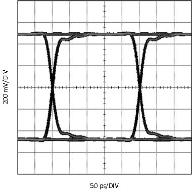 Figure 8-4 Eye Measured at Point (A)
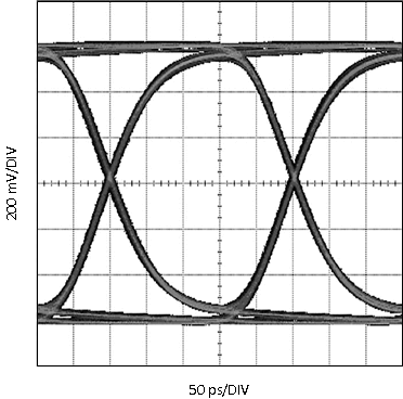 Figure 8-6 Eye Measured at Point (C), Pre-Emph = 0 dB
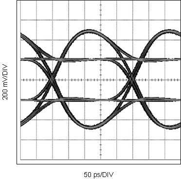 Figure 8-8 Eye Measured at Point (C), Pre-Emph = –9 dB
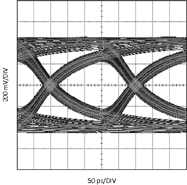 Figure 8-5 Eye Measured at Point (B)
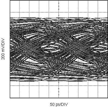 Figure 8-7 Eye Measured at Point (D), Pre-Emph = 0 dB
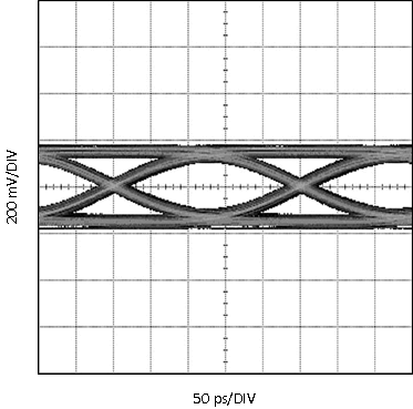 Figure 8-9 Eye Measured at Point (D), Pre-Emph = –9 dB