SNVSB32B August 2018 – June 2021 LM5146-Q1
PRODUCTION DATA
- 1 Features
- 2 Applications
- 3 Description
- 4 Revision History
- 5 Description (continued)
- 6 Pin Configuration and Functions
- 7 Specifications
-
8 Detailed Description
- 8.1 Overview
- 8.2 Functional Block Diagram
- 8.3
Feature Description
- 8.3.1 Input Range (VIN)
- 8.3.2 Output Voltage Setpoint and Accuracy (FB)
- 8.3.3 High-Voltage Bias Supply Regulator (VCC)
- 8.3.4 Precision Enable (EN/UVLO)
- 8.3.5 Power Good Monitor (PGOOD)
- 8.3.6 Switching Frequency (RT, SYNCIN)
- 8.3.7 Configurable Soft Start (SS/TRK)
- 8.3.8 Voltage-Mode Control (COMP)
- 8.3.9 Gate Drivers (LO, HO)
- 8.3.10 Current Sensing and Overcurrent Protection (ILIM)
- 8.3.11 OCP Duty Cycle Limiter
- 8.4 Device Functional Modes
- 9 Application and Implementation
- 10Power Supply Recommendations
- 11Layout
- 12Device and Documentation Support
- 13Mechanical, Packaging, and Orderable Information
Package Options
Refer to the PDF data sheet for device specific package drawings
Mechanical Data (Package|Pins)
- RGY|20
Thermal pad, mechanical data (Package|Pins)
- RGY|20
Orderable Information
8.3.6.2 Clock Synchronization
Apply an external clock synchronization signal to the LM5146-Q1 to synchronize switching in both frequency and phase. Requirements for the external clock SYNC signal are:
- Clock frequency range: 100 kHz to 1 MHz
- Clock frequency: –20% to +50% of the free-running frequency set by RRT
- Clock maximum voltage amplitude: 13 V
- Clock minimum pulse width: 50 ns
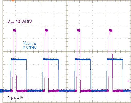
 Figure 8-5 Typical 400-kHz SYNCIN and SW
Voltage Waveforms
Figure 8-5 Typical 400-kHz SYNCIN and SW
Voltage WaveformsFigure 8-5 shows a clock signal at 400 kHz and the corresponding SW node waveform (VIN = 48 V, VOUT = 5 V, free-running frequency = 280 kHz). The SW voltage waveform is synchronized with respect to the rising edge of SYNCIN. The rising edge of the SW voltage is phase delayed relative to SYNCIN by approximately 100 ns.