-
LP3850x-ADJ, LP3850xA-ADJ 1.5-A Flexcap Low-Dropout Linear Regulator for 2.7-V to 5.5-V Inputs SNVS539H November 2007 – September 2015 LP38500-ADJ , LP38502-ADJ
PRODUCTION DATA.
-
LP3850x-ADJ, LP3850xA-ADJ 1.5-A Flexcap Low-Dropout Linear Regulator for 2.7-V to 5.5-V Inputs
- 1 Features
- 2 Applications
- 3 Description
- 4 Revision History
- 5 Pin Configurations and Functions
- 6 Specifications
- 7 Detailed Description
- 8 Application and Implementation
- 9 Power Supply Recommendations
- 10Layout
- 11Device and Documentation Support
- 12Mechanical, Packaging, and Orderable Information
- IMPORTANT NOTICE
Package Options
Mechanical Data (Package|Pins)
Thermal pad, mechanical data (Package|Pins)
- KTT|5
Orderable Information
LP3850x-ADJ, LP3850xA-ADJ 1.5-A Flexcap Low-Dropout Linear Regulator for 2.7-V to 5.5-V Inputs
1 Features
- Input Voltage: 2.7 V to 5.5 V
- Adjustable Output Voltage: 0.6 V to 5 V
- FlexCap: Stable with Ceramic, Tantalum, or Aluminum Capacitors
- Stable with 10-µF Input and Output Capacitors
- Low Ground-Pin Current
- 25-nA Quiescent Current in Shutdown Mode
- Ensured Output Current of 1.5 A
- Ensured VADJ Accuracy of ±1.5% at 25°C (A Grade)
- Ensured Accuracy of ±3.5% at 25°C (STD)
- Overtemperature and Overcurrent Protection
- ENABLE Pin (LP38502)
2 Applications
- ASIC Power Supplies In:
- Printers, Graphics Cards, DVD Players
- Set Top Boxes, Copiers, Routers
- DSP and FPGA Power Supplies
- SMPS Regulator
- Conversion from 3.3-V or 5-V Rail
3 Description
TI's FlexCap low-dropout (LDO) linear regulators feature unique compensation that allow use of any type of output capacitor with no limits on minimum or maximum equivalent series resistance (ESR). The LP38500 and LP38502 series of LDOs operates from a 2.7-V to 5.5-V input supply. These ultra-low-dropout linear regulators respond very quickly to step changes in load, making them suitable for low-voltage microprocessor applications. Developed on a CMOS process (utilizing a PMOS pass transistor) the LP38500-ADJ and LP38502-ADJ have low quiescent currents that changes little with load current.
- GND Pin Current: Typically 2 mA at 1.5-A load current.
- Disable Mode: Typically 25-nA quiescent current when the EN pin is pulled low. (LP38502-ADJ)
- Simplified Compensation: Stable with any type of output capacitor, regardless of ESR.
- Precision Output: A grade versions available with 1.5% VADJ tolerance (25°C) and 3% over line, load, and temperature.
Device Information(1)
| PART NUMBER | PACKAGE | BODY SIZE (NOM) |
|---|---|---|
| LP38500 LP38502 |
DDPAK/TO-263 (5) | 10.16 mm x 8.42 mm |
| TO-263 (5) | 10.16 mm x 9.85 mm | |
| WSON (8) | 3.00 mm x 2.50 mm |
- For all available packages, see the orderable addendum at the end of the datasheet.
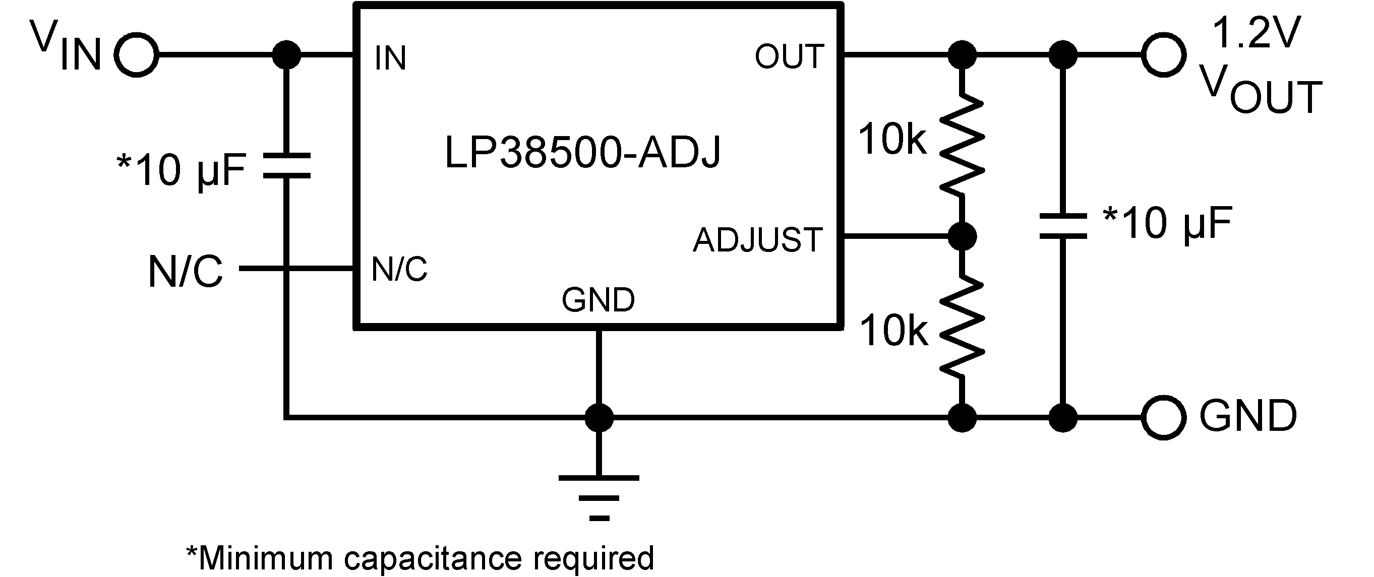
Typical Circuit (LP38500)

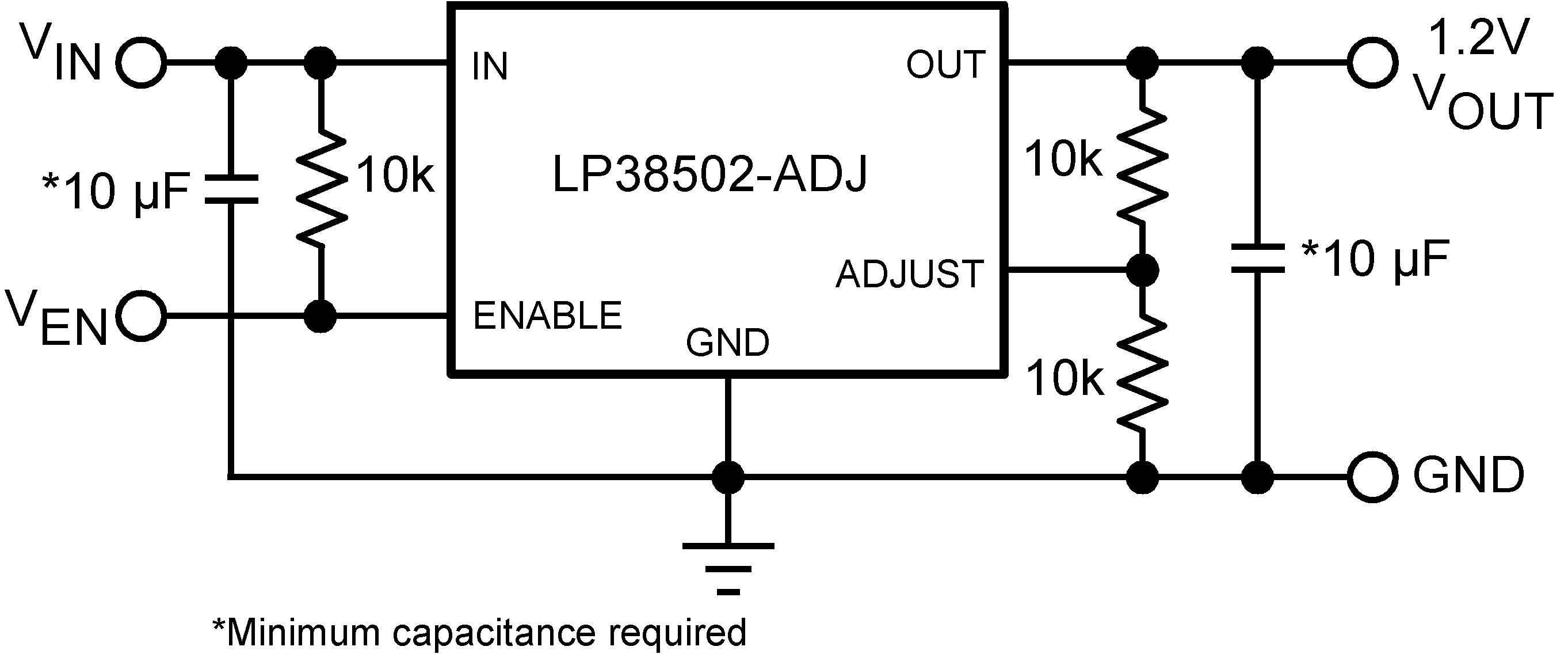
Typical Circuit (LP38502)

4 Revision History
Changes from G Revision (June 2015) to H Revision
- Changed thermal values for KTT (DDPAK/TO-263); add notes 2 and 3 to Thermal Information table Go
Changes from F Revision (April 2013) to G Revision
- Added Added Device Information and Pin Configuration and Functions sections, ESD Ratings and updated Thermal Information tables, Feature Description, Device Functional Modes, Application and Implementation, Power Supply Recommendations, Layout, Device and Documentation Support , and Mechanical, Packaging, and Orderable Information sections.Go
- Changed format of EC table Go
- Deleted obsolete heatsinking information for DDPAK/TO-263 package Go
Changes from E Revision (April 2013) to F Revision
- Changed layout of National Data Sheet to TI formatGo
5 Pin Configurations and Functions


Pin Functions
| PIN | TYPE | DESCRIPTION | |||
|---|---|---|---|---|---|
| NAME | KTT | NDQ | NGS | ||
| ADJ | 5 | 5 | 8 | O | Sets output voltage |
| EN | 1 | 1 | 2 | I | Enable (LP38502-ADJ only). Pull high to enable the output, low to disable the output. This pin has no internal bias and must be either tied to the input voltage, or actively driven. |
| GND | 3 | 3 | 1 | G | Ground |
| IN | — | — | 2 | I | Input supply (LP38500-ADJ only). Input supply pins share current and must be connected together on the PC board. |
| IN | 2 | 2 | 3, 4 | I | Input supply. Input Supply pins share current and must be connected together on the PC board. |
| N/C | 1 | 1 | — | — | In the LP38500-ADJ, this pin has no internal connections. It can be left floating or used for trace routing. |
| OUT | 4 | 4 | 5, 6, 7 | O | Regulated output voltage. Output pins share current and must be connected together on the PC board. |
| DAP | √ | √ | √ | — | The DAP is used to remove heat from the device by conducting it to a copper clad area on the PCB which acts as a heatsink. The DAP is electrically connected to the backside of the die. The DAP must be connected to ground potential, but can not be used as the only ground connection. |
6 Specifications
6.1 Absolute Maximum Ratings
over operating free-air temperature range (unless otherwise noted)(1)(2)| MIN | MAX | UNIT | ||
|---|---|---|---|---|
| Input pin voltage (survival) | −0.3 | 6 | V | |
| Enable pin voltage (survival) | −0.3 | 6 | V | |
| Output pin voltage (survival) | −0.3 | 6 | V | |
| IOUT (survival) | Internally limited | |||
| Power dissipation(3) | Internally limited | |||
| Storage temperature, Tstg | −65 | 150 | °C | |
6.2 ESD Ratings
| VALUE | UNIT | |||
|---|---|---|---|---|
| VESD | Electrostatic discharge | Human body model (HBM), per ANSI/ESDA/JEDEC JS-001, all pins(1) | ±2000 | V |
6.3 Recommended Operating Conditions
over operating free-air temperature range (unless otherwise noted)(1)| MIN | NOM | MAX | UNIT | ||
|---|---|---|---|---|---|
| Input supply voltage | 2.7 | 5.5 | V | ||
| Enable input voltage | 0 | 5.5 | V | ||
| Output current (DC) | 0 | 1.5 | A | ||
| VOUT | 0.6 | 5 | V | ||
| Junction temperature(1) | −40 | 125 | °C | ||
6.4 Thermal Information
| THERMAL METRIC(1) | LP38500 and LP38502 | UNIT | |||
|---|---|---|---|---|---|
| KTT(DDPAK/TO-263) | NDQ (TO-263) | NGS (WSON) | |||
| 5 PINS | 5 PINS | 8 PINS | |||
| RθJA(2) | Junction-to-ambient thermal resistance | 41.8 | 33.3 | 52.5(3) | °C/W |
| RθJC(top) | Junction-to-case (top) thermal resistance | 45.0 | 22.1 | 53.6 | °C/W |
| RθJB | Junction-to-board thermal resistance | 24.8 | 16.9 | 26.1 | °C/W |
| ψJT | Junction-to-top characterization parameter | 13.1 | 5.8 | 0.6 | °C/W |
| ψJB | Junction-to-board characterization parameter | 23.8 | 16.8 | 26.3 | °C/W |
| RθJC(bot) | Junction-to-case (bottom) thermal resistance | 2.4 | 2.3 | 7.4 | °C/W |
6.5 Electrical Characteristics
Unless otherwise specified VIN = 3.3 V, IOUT = 10 mA, CIN = 10 μF, COUT = 10 μF, VEN = VIN, VOUT = 1.8 V. Minimum and maximum limits apply over the junction temperature (TJ) range of –40°C to +125°C and are specified through test, design, or statistical correlation. Typical values represent the most likely parametric norm at TJ = 25°C, and are provided for reference purposes only.| PARAMETER | TEST CONDITIONS | MIN | TYP | MAX | UNIT | |
|---|---|---|---|---|---|---|
| VADJ | Adjust pin voltage(1) | 2.7 V ≤ VIN ≤ 5.5 V 10 mA ≤ IOUT ≤ 1.5 A TJ = 25°C |
0.584 | 0.605 | 0.626 | V |
| 2.7 V ≤ VIN ≤ 5.5 V 10 mA ≤ IOUT ≤ 1.5 A |
0.575 | 0.635 | ||||
| VADJ | Adjust pin voltage (A grade)(1) | 2.7 V ≤ VIN ≤ 5.5 V 10 mA ≤ IOUT ≤ 1.5 A TJ = 25°C |
0.596 | 0.605 | 0.614 | V |
| 2.7 V ≤ VIN ≤ 5.5 V 10 mA ≤ IOUT ≤ 1.5 A |
0.587 | 0.623 | ||||
| IADJ | ADJUST pin bias current | 2.7 V ≤ VIN ≤ 5.5 V TJ = 25°C |
50 | nA | ||
| 2.7 V ≤ VIN ≤ 5.5 V | 750 | nA | ||||
| VDO | Dropout voltage(2) | IOUT = 1.5 A TJ = 25°C |
220 | 275 | mV | |
| IOUT = 1.5 A | 375 | mV | ||||
| ΔVOUT / ΔVIN | Output voltage line regulation(1)(3) | 2.7 V ≤ VIN ≤ 5.5 V TJ = 25°C |
0.04 | %/V | ||
| 2.7 V ≤ VIN ≤ 5.5 V | 0.05 | %/V | ||||
| ΔVOUT / ΔIOUT | Output voltage load regulation(1) (4) | 10 mA < IOUT < 1.5 A TJ = 25°C |
0.18 | %/A | ||
| 10 mA < IOUT < 1.5 A | 0.33 | %/A | ||||
| IGND | Ground pin current in normal operation mode | 10 mA < IOUT < 1.5 A TJ = 25°C |
2 | 3.5 | mA | |
| 10 mA < IOUT < 1.5 A | 4.5 | |||||
| IDISABLED | Ground pin current | VEN < VIL(EN), TJ = 25°C | 0.025 | 0.125 | µA | |
| VEN < VIL(EN) | 15 | |||||
| IOUT(PK)GND | Peak output current | VOUT ≥ VOUT(NOM) – 5% | 3.6 | A | ||
| ISC | Short-circuit current | VOUT = 0 V, TJ = 25°C | 3.7 | A | ||
| VOUT = 0 V | 2 | |||||
| ENABLE INPUT (LP38502 Only) | ||||||
| VIH(EN) | Enable logic high | VOUT = ON | 1.4 | V | ||
| VIL(EN) | Enable logic low | VOUT = OFF | 0.65 | V | ||
| td(off) | Turnoff delay | Time from VEN < VIL(EN) to VOUT = OFF ILOAD = 1.5 A |
25 | µs | ||
| td(on) | Turnon delay | Time from VEN >VIH(EN) to VOUT = ON ILOAD = 1.5A |
25 | µs | ||
| IIH(EN) | Enable pin high current | VEN = VIN | 1 | nA | ||
| IIL(EN) | Enable pin low current | VEN = 0 V | 0.1 | |||
| AC PARAMETERS | ||||||
| PSRR | Ripple rejection | VIN = 3 V, IOUT = 1.5 A, ƒ = 120 Hz | 58 | dB | ||
| VIN = 3 V, IOUT = 1.5 A, ƒ = 1 kHz | 56 | |||||
| ρn(l/f) | Output noise density | ƒ = 120 Hz, COUT = 10 µF CER | 1 | µV/√Hz | ||
| en | Output noise voltage | BW = 100 Hz – 100 kHz COUT = 10 µF CER |
100 | µV(rms) | ||
| THERMALS | ||||||
| TSD | Thermal shutdown | TJ rising | 170 | — | °C | |
| ΔTSD | Thermal shutdown hysteresis | TJ falling from TSD | 10 | — | °C | |
6.6 Typical Characteristics
Unless otherwise specified: TJ = 25°C, VIN = 2.7 V, VEN = VIN, CIN = 10 µF, COUT = 10 µF, IOUT = 10 mA, VOUT = 1.8 V.


