SNVS056J May 2000 – June 2015 LP3961 , LP3964
PRODUCTION DATA.
- 1 Features
- 2 Applications
- 3 Description
- 4 Revision History
- 5 Pin Configurations and Functions
- 6 Specifications
- 7 Detailed Description
-
8 Application and Implementation
- 8.1 Application Information
- 8.2
Typical Applications
- 8.2.1 Design Requirements
- 8.2.2
Detailed Design Procedure
- 8.2.2.1 External Capacitors
- 8.2.2.2 Selecting a Capacitor
- 8.2.2.3 Capacitor Characteristics
- 8.2.2.4 RFI and EMI Susceptibility
- 8.2.2.5 Output Adjustment
- 8.2.2.6 Turnon Characteristics for Output Voltages Programmed to 2.0 V or Below
- 8.2.2.7 Output Noise
- 8.2.2.8 Shutdown Operation
- 8.2.2.9 Maximum Output Current Capability
- 8.2.3 Application Curves
- 9 Power Supply Recommendations
- 10Layout
- 11Device and Documentation Support
- 12Mechanical, Packaging, and Orderable Information
Package Options
Mechanical Data (Package|Pins)
Thermal pad, mechanical data (Package|Pins)
- KTT|5
Orderable Information
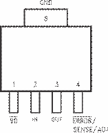
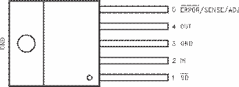
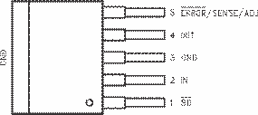
5 Pin Configurations and Functions
SOT-223 Package
5-Pin NDC
Top View

TO-220 Package (LP3964)
5-Pin NDH
Top View

SFM/TO-263 Package
5-Pin KTT
Top View
