SBOSA00B December   2019  – August 2020 OPA1637

PRODUCTION DATA  

  1. Features
  2. Applications
  3. Description
  4. Revision History
  5. Pin Configuration and Functions
  6. Specifications
    1. 6.1 Absolute Maximum Ratings
    2. 6.2 ESD Ratings
    3. 6.3 Recommended Operating Conditions
    4. 6.4 Thermal Information
    5. 6.5 Electrical Characteristics
    6. 6.6 Typical Characteristics
  7. Parameter Measurement Information
    1. 7.1 Characterization Configuration
  8. Detailed Description
    1. 8.1 Overview
    2. 8.2 Functional Block Diagram
    3. 8.3 Feature Description
      1. 8.3.1 Super-Beta Input Bipolar Transistors
      2. 8.3.2 Power Down
      3. 8.3.3 Flexible Gain Setting
      4. 8.3.4 Amplifier Overload Power Limit
    4. 8.4 Device Functional Modes
  9. Application and Implementation
    1. 9.1 Application Information
      1. 9.1.1 Driving Capacitive Loads
      2. 9.1.2 Operating the Power-Down Feature
      3. 9.1.3 I/O Headroom Considerations
      4. 9.1.4 Noise Performance
    2. 9.2 Typical Applications
      1. 9.2.1 Current-Output Audio DAC Buffer to Class-D Amplifier
        1. 9.2.1.1 Design Requirements
        2. 9.2.1.2 Detailed Design Procedure
        3. 9.2.1.3 Application Curves
      2. 9.2.2 An MFB Filter Driving an ADC Application
        1. 9.2.2.1 Design Requirements
        2. 9.2.2.2 Detailed Design Procedure
        3. 9.2.2.3 Application Curves
      3. 9.2.3 Differential Microphone Input to Line Level
        1. 9.2.3.1 Application Curves
  10. 10Power Supply Recommendations
  11. 11Layout
    1. 11.1 Layout Guidelines
      1. 11.1.1 Board Layout Recommendations
    2. 11.2 Layout Example
  12. 12Device and Documentation Support
    1. 12.1 Device Support
      1. 12.1.1 Development Support
    2. 12.2 Documentation Support
      1. 12.2.1 Related Documentation
    3. 12.3 Receiving Notification of Documentation Updates
    4. 12.4 Support Resources
    5. 12.5 Trademarks
    6. 12.6 Electrostatic Discharge Caution
    7. 12.7 Glossary
  13. 13Mechanical, Packaging, and Orderable Information

Package Options

Mechanical Data (Package|Pins)
Thermal pad, mechanical data (Package|Pins)
Orderable Information

Differential Microphone Input to Line Level

Professional dynamic microphones typically feature low output impedance to minimize noise coupling on the microphone cable. Interfacing the microphone with high-impedance circuitry typically requires the use of an impedance conversion stage, often done with a transformer or discrete amplifiers. The flexibility of the OPA1637 allows the device to be configured with a low differential input impedance and 20 dB of gain, simplifying the impedance conversion and gain stage into a single device. Figure 9-10 shows an example of a differential, low input impedance, microphone level voltage (10 mV to 100 mV) amplifier to a line-level amplitude signal that also has adjustable dc common-mode shift capability. This design example shows how the OPA1637 makes a great choice for driving an ADC class-D amplifier.
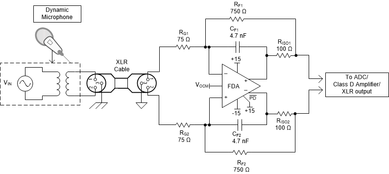
GUID-12F31A2F-CA4F-4D17-8482-DB04C9B2E4B1-low.gifFigure 9-10 Fully Differential, Low-Noise, 20-dB Microphone Gain Block With DC Shift