SBOS058B December 1997 – November 2024 OPA134 , OPA2134 , OPA4134
PRODUCTION DATA
- 1
- 1 Features
- 2 Applications
- 3 Description
- 4 Pin Configuration and Functions
- 5 Specifications
- 6 Detailed Description
- 7 Application and Implementation
- 8 Device and Documentation Support
- 9 Revision History
- 10Mechanical, Packaging, and Orderable Information
Package Options
Refer to the PDF data sheet for device specific package drawings
Mechanical Data (Package|Pins)
- D|8
- P|8
Thermal pad, mechanical data (Package|Pins)
Orderable Information
6.2.3 Source Impedance and Distortion
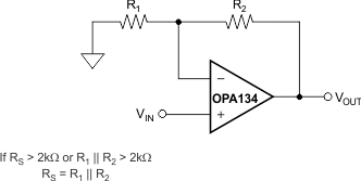
For lowest distortion with a source or feedback network with an impedance greater than 2kΩ, match the impedance seen by the positive and negative inputs in noninverting applications. The p-channel JFETs in the FET input stage exhibit a varying input capacitance with applied common-mode input voltage. In inverting configurations, the input does not vary with input voltage, because the inverting input is held at virtual ground. However, in noninverting applications the inputs do vary, and the gate-to-source voltage is not constant. The effect is increased distortion due to the varying capacitance for unmatched source impedances greater than 2kΩ.
To maintain low distortion, match unbalanced source impedance with the appropriate values in the feedback network as shown in Figure 6-2. Of course, the unbalanced impedance can be from gain-setting resistors in the feedback path. If the parallel combination of R1 and R2 is greater than 2kΩ, use a matching impedance on the noninverting input. As always, minimize resistor values to reduce the effects of thermal noise.
 Figure 6-2 Impedance
Matching for Maintaining Low Distortion in Noninverting Circuits