SBOS771B December 2016 – November 2024 OPA4277-SP
PRODUCTION DATA
- 1
- 1 Features
- 2 Applications
- 3 Description
- 4 Pin Configuration and Functions
- 5 Specifications
- 6 Detailed Description
- 7 Application and Implementation
- 8 Device and Documentation Support
- 9 Revision History
- 10Mechanical, Packaging, and Orderable Information
Package Options
Refer to the PDF data sheet for device specific package drawings
Mechanical Data (Package|Pins)
- JDJ|28
- HFR|14
- KGD|0
Thermal pad, mechanical data (Package|Pins)
Orderable Information
4.1 Bare Die Information
| DIE THICKNESS | BACKSIDE FINISH | BACKSIDE POTENTIAL | BOND PAD METALLIZATION COMPOSITION | BOND PAD THICKNESS |
|---|---|---|---|---|
| 15 mils | Silicon with backgrind | Negative (lower) power supply | AlCu (0.5%) | 990 nm to 1210 nm |

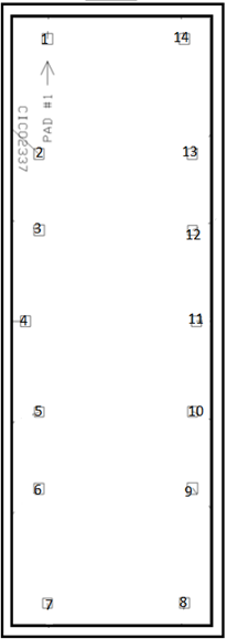
Table 4-3 Bond Pad Coordinates in Microns
| PAD(1) | TYPE | DESCRIPTION | X MIN | Y MIN | X MAX | Y MAX | |
|---|---|---|---|---|---|---|---|
| NO. | NAME | ||||||
| 1 | OUT A | Output | Output channel A | 1791.042 | 7290.340 | 1901.751 | 7401.049 |
| 2 | –IN A | Input | Inverting input channel A | 1701.719 | 6111.536 | 1807.397 | 6217.213 |
| 3 | +IN A | Input | Noninverting input channel A | 1701.719 | 5326.505 | 1812.429 | 5437.215 |
| 4 | V+ | — | Positive (higher) power supply | 1555.784 | 4390.507 | 1661.461 | 4498.700 |
| 5 | +IN B | Input | Noninverting input channel B | 1706.752 | 3462.057 | 1807.397 | 3562.702 |
| 6 | –IN B | Input | Inverting input channel B | 1701.719 | 2671.994 | 1807.397 | 2777.671 |
| 7 | OUT B | Output | Output channel B | 1796.074 | 1498.222 | 1896.719 | 1598.867 |
| 8 | OUT C | Output | Output channel C | 3278.071 | 1498.222 | 3383.748 | 1603.900 |
| 9 | –IN C | Input | Inverting input channel C | 3362.361 | 2671.994 | 3473.071 | 2782.704 |
| 10 | +IN C | Input | Noninverting input channel C | 3367.393 | 3462.057 | 3473.071 | 3567.734 |
| 11 | V– | — | Negative (lower) power supply | 3407.651 | 4391.765 | 3513.329 | 4497.442 |
| 12 | +IN D | Input | Noninverting input channel D | 3367.393 | 5331.537 | 3468.038 | 5432.182 |
| 13 | –IN D | Input | Inverting input channel D | 3362.361 | 6111.536 | 3468.038 | 6217.213 |
| 14 | OUT D | Output | Output channel D | 3273.039 | 7290.340 | 3383.748 | 7401.049 |
(1) Substrate must be biased to V–, negative (lower) power
supply.