SLLS740C March 2007 – February 2024 SN65C1167E , SN65C1168E
PRODUCTION DATA
- 1
- 1 Features
- 2 Applications
- 3 Description
- 4 Pin Configuration and Functions
-
5 Specifications
- 5.1 Absolute Maximum Ratings
- 5.2 Driver Output and Receiver Input ESD Ratings
- 5.3 Recommended Operating Conditions
- 5.4 Thermal Information
- 5.5 Driver Section Electrical Characteristics
- 5.6 Receiver Section Electrical Characteristics
- 5.7 Driver Section Switching Characteristics
- 5.8 Receiver Section Switching Characteristics
- 6 Parameter Measurement Information
- 7 Detailed Description
- 8 Application and Implementation
- 9 Device and Documentation Support
- 10Revision History
- 11Mechanical, Packaging, and Orderable Information
Package Options
Mechanical Data (Package|Pins)
Thermal pad, mechanical data (Package|Pins)
- RGY|16
Orderable Information
3 Description
The SN65C1167E and SN65C1168E consist of dual drivers and dual receivers with ±15kV ESD (Human Body Model [HBM]) and ±8-kV ESD (IEC61000-4-2 Air-Gap Discharge and Contact Discharge) for RS-422 bus pins. The devices meet the requirements of TIA/EIA-422-B and ITU recommendation V.11.
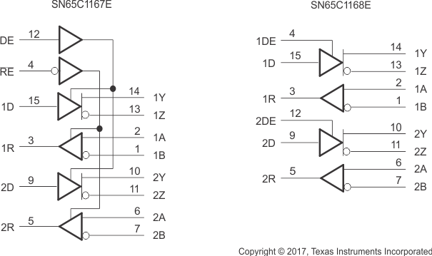
The SN65C1167E combines dual 3-state differential line drivers and 3-state differential line receivers, both of which operate from a single 5V power supply. The driver and receiver have active-high and active-low enables, respectively, which can be connected together externally to function as direction control.
SN65C1168E drivers have individual active-high enables.
| PART NUMBER | PACKAGE(1) | PACKAGE SIZE(2) |
|---|---|---|
| SN65C116xE | SO (16) | 10.3mm × 5.3mm |
| TSSOP (16) | 5mm × 4.4mm | |
| VQFN (16) | 4mm × 3.5mm |
 Block Diagram