-
SNx4HC164 8-Bit Parallel-Out Serial Shift Registers
- 1 Features
- 2 Applications
- 3 Description
- 4 Revision History
- 5 Device Comparison Table
- 6 Pin Configuration and Functions
-
7 Specifications
- 7.1 Absolute Maximum Ratings
- 7.2 ESD Ratings
- 7.3 Recommended Operating Conditions
- 7.4 Thermal Information
- 7.5 Electrical Characteristics, TA = 25°C
- 7.6 Electrical Characteristics, TA = -55°C to 125°C
- 7.7 Electrical Characteristics, TA = -55°C to 85°C
- 7.8 Timing Requirements, TA = 25°C
- 7.9 Timing Requirements, TA = -55°C to 125°C
- 7.10 Timing Requirements, TA = -55°C to 85°C
- 7.11 Switching Characteristics, TA = 25°C
- 7.12 Switching Characteristics, TA = -55°C to 125°C
- 7.13 Switching Characteristics, TA = -55°C to 85°C
- 8 Parameter Measurement Information
- 9 Detailed Description
- 10Application and Implementation
- 11Power Supply Recommendations
- 12Layout
- 13Device and Documentation Support
- 14Mechanical, Packaging, and Orderable Information
- IMPORTANT NOTICE
Package Options
Refer to the PDF data sheet for device specific package drawings
Mechanical Data (Package|Pins)
- D|14
- PW|14
- N|14
- NS|14
Thermal pad, mechanical data (Package|Pins)
Orderable Information
SNx4HC164 8-Bit Parallel-Out Serial Shift Registers
1 Features
- Wide Operating Voltage Range of 2 V to 6 V
- Outputs Can Drive Up to 10 LSTTL Loads
- Low Power Consumption, 80-μA Maximum ICC
- Typical tpd = 20 ns
- ±4-mA Output Drive at 5 V
- Low Input Current of 1-μA Maximum
- AND-Gated (Enable/Disable) Serial Inputs
- Fully Buffered Clock and Serial Inputs
- Direct Clear
-
On Products Compliant to MIL-PRF-38535,
All Parameters Are Tested Unless Otherwise Noted. On All Other Products, Production Processing Does Not Necessarily Include Testing of All Parameters.
2 Applications
- Programable Logic Controllers
- Appliances
- Video Display Systems
- Output Expander
3 Description
These 8-bit shift registers feature AND-gated serial inputs and an asynchronous clear (CLR) input. The gated serial (A and B) inputs permit complete control over incoming data; a low at either input inhibits entry of the new data and resets the first flip-flop to the low level at the next clock (CLK) pulse. A high-level input enables the other input, which then determines the state of the first flip-flop. Data at the serial inputs can be changed while CLK is high or low, provided the minimum set-up time requirements are met. Clocking occurs on the low-to-high-level transition of CLK.
Device Information(1)
| PART NUMBER | PACKAGE | BODY SIZE (NOM) |
|---|---|---|
| SN74HC164 | SOIC (14) | 8.65 mm × 3.91 mm |
| PDIP (14) | 19.30 mm × 6.35 mm | |
| SO (14) | 10.30 mm × 5.30 mm | |
| TSSOP (14) | 5.00 mm × 4.40 mm | |
| SN54HC164 | CDIP (14) | 19.94 mm × 6.92 mm |
| CFP (14) | 9.21 mm × 6.29 mm | |
| LCCC (14) | 9.39 mm × 9.39 mm |
- For all available packages, see the orderable addendum at the end of the data sheet.
Logic Diagram (Positive Logic)

4 Revision History
Changes from F Revision (October 2013) to G Revision
- Added Applications section, Device Information table, Pin Configuration and Functions section, ESD Ratings table, Thermal Information table, Typical Characteristics section, Feature Description section, Device Functional Modes, Application and Implementation section, Power Supply Recommendations section, Layout section, Device and Documentation Support section, and Mechanical, Packaging, and Orderable Information sectionGo
- Added Military Disclaimer to Features list.Go
- Added Handling Ratings table.Go
Changes from E Revision (November 2010) to F Revision
5 Device Comparison Table
| PART NUMBER | PACKAGE | BODY SIZE (NOM) |
|---|---|---|
| SN74HC164D | SOIC (14) | 8.65 mm × 3.91 mm |
| SN74HC164N | PDIP (14) | 19.30 mm × 6.35 mm |
| SN74HC164NS | SO (14) | 10.30 mm × 5.30 mm |
| SN74HC164PW | TSSOP (14) | 5.00 mm × 4.40 mm |
| SN54HC164J | CDIP (14) | 19.94 mm × 6.92 mm |
| SN54HC164W | CFP (14) | 9.21 mm × 6.29 mm |
| SN54HC164FK | LCCC (14) | 9.39 mm × 9.39 mm |
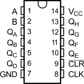
6 Pin Configuration and Functions

Pin Functions
| PIN | I/O | DESCRIPTION | |
|---|---|---|---|
| SOIC, PDIP, SO, CDIP, CFP, or TSSOP NO. | NAME | ||
| 1 | A | I | Gated Serial Input 1 |
| 2 | B | I | Gated Serial Input 2 |
| 3 | QA | O | Parallel Output |
| 4 | QB | O | Parallel Output |
| 5 | QC | O | Parallel Output |
| 6 | QD | O | Parallel Output |
| 7 | GND | - | Ground |
| 8 | CLK | I | Clock |
| 9 | CLR | I | Clear 1 Active-Low |
| 10 | QE | O | Parallel Output |
| 11 | QF | O | Parallel Output |
| 12 | QG | O | Parallel Output |
| 13 | QH | O | Parallel Output |
| 14 | VCC | — | Power |

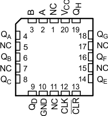
Pin Functions
| PIN | I/O | DESCRIPTION | |
|---|---|---|---|
| LCCC NO. | NAME | ||
| 1 | NC | — | No Connect |
| 2 | A | I | Gated Serial Input 1 |
| 3 | B | I | Gated Serial Input 2 |
| 4 | QA | O | Parallel Output |
| 5 | NC | — | No Connect |
| 6 | QB | O | Parallel Output |
| 7 | NC | — | No Connect |
| 8 | QC | O | Parallel Output |
| 9 | QD | O | Parallel Output |
| 10 | GND | — | Ground |
| 11 | NC | — | No Connect |
| 12 | CLK | I | Clock |
| 13 | CLR | I | Clear 1 Active-Low |
| 14 | QE | O | Parallel Output |
| 15 | NC | — | No Connect |
| 16 | QF | O | Parallel Output |
| 17 | NC | — | No Connect |
| 18 | QG | O | Parallel Output |
| 19 | QH | O | Parallel Output |
| 20 | VCC | — | Power |