SLOS217I July 1998 – December 2024 THS3001
PRODUCTION DATA
- 1
- 1 Features
- 2 Applications
- 3 Description
- 4 Pin Configuration and Functions
- 5 Specifications
- 6 Detailed Description
- 7 Application and Implementation
- 8 Device and Documentation Support
- 9 Revision History
- 10Mechanical, Packaging, and Orderable Information
Package Options
Refer to the PDF data sheet for device specific package drawings
Mechanical Data (Package|Pins)
- D|8
- DGN|8
Thermal pad, mechanical data (Package|Pins)
- DGN|8
Orderable Information
7.2.1 General Configurations
A common error for the first-time CFB user is the creation of a unity gain buffer amplifier by shorting the output directly to the inverting input. A CFB amplifier in this configuration can oscillate and is not recommended. The THS3001, like all CFB amplifiers, must have a feedback resistor for stable operation. Additionally, placing capacitors directly from the output to the inverting input is not recommended. This is because, at high frequencies, a capacitor has a low impedance. This results in an unstable amplifier when using a current-feedback amplifier. Because of this, integrators and simple low-pass filters, which are easily implemented on a VFB amplifier, have to be designed slightly differently. If filtering is required, simply place an RC-filter at the noninverting terminal of the operational-amplifier (see Figure 7-5).
 Figure 7-5 Single-Pole Low-Pass
Filter
Figure 7-5 Single-Pole Low-Pass
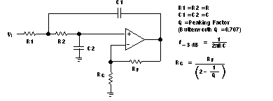
FilterIf a multiple-pole filter is required, the use of a Sallen-Key filter can work well with CFB amplifiers. This is because the filtering elements are not in the negative feedback loop and stability is not compromised. A CFB amplifier high slew rate and bandwidth can create accurate signals and help minimize distortion. An example is shown in Figure 7-6.
 Figure 7-6 2-Pole Low-Pass Sallen-Key
Filter
Figure 7-6 2-Pole Low-Pass Sallen-Key
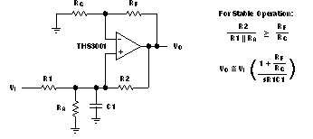
FilterThere are two simple ways to create an integrator with a CFB amplifier. The first, shown in Figure 7-7, adds a resistor in series with the capacitor. This is acceptable because at high frequencies, the resistor is dominant and the feedback impedance never drops below the resistor value. The second, shown in Figure 7-8, uses positive feedback to create the integration. Caution is advised because oscillations can occur due to the positive feedback.
 Figure 7-7 Inverting CFB
Integrator
 Figure 7-8 Noninverting CFB
Integrator
Figure 7-8 Noninverting CFB
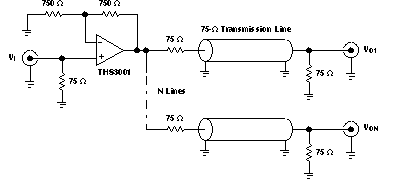
IntegratorThe THS3001 can also be employed as a good video distribution amplifier. One characteristic of distribution amplifiers is the fact that the differential phase (DP) and the differential gain (DG) are compromised as the number of lines increases and the closed-loop gain increases (see Figures 22 to 25 for more information). Be sure to use termination resistors throughout the distribution system to minimize reflections and capacitive loading.
 Figure 7-9 Video Distribution Amplifier
Application