-
TLV62585 3-A High Efficiency Synchronous Buck Converter in QFN or SOT563 Package
- 1 Features
- 2 Applications
- 3 Description
- 4 Revision History
- 5 Pin Configuration and Functions
- 6 Specifications
- 7 Detailed Description
- 8 Application and Implementation
- 9 Power Supply Recommendations
- 10Layout
- 11Device and Documentation Support
- 12Mechanical, Packaging, and Orderable Information
- IMPORTANT NOTICE
Package Options
Mechanical Data (Package|Pins)
Thermal pad, mechanical data (Package|Pins)
Orderable Information
TLV62585 3-A High Efficiency Synchronous Buck Converter in QFN or SOT563 Package
1 Features
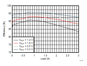
- Up to 95% efficiency
- Low RDS(ON) power switches 56 mΩ / 32 mΩ
- 2.5-V to 5.5-V input voltage range
- Adjustable output voltage from 0.6-V to VIN
- Power save mode for light load efficiency
- 100% duty cycle for lowest dropout
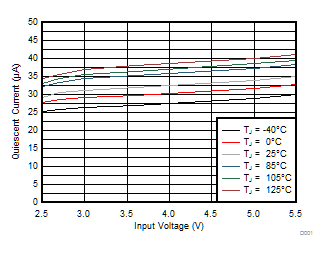
- 35-μA operating quiescent current
- 1.5-MHz typical switching frequency
- Short circuit protection (HICCUP)
- Output discharge
- Power good output
- Thermal shutdown protection
- Available in 2-mm × 2-mm QFN or 1.6-mm x 1.6-mm SOT563 package
- Create a custom design using the TLV62585 with the WEBENCH® Power Designer
3 Description
The TLV62585 device is a high-frequency synchronous step-down converter optimized for compact solution size and high efficiency. The device integrates switches capable of delivering an output current up to 3 A. At medium to heavy loads, the converter operates in pulse width modulation (PWM) mode with typical 1.5-MHz switching frequency. At light load, the device automatically enters Power Save Mode (PSM) to maintain high efficiency over the entire load current range. In shutdown, the current consumption is reduced to less than 2 μA.
The internal compensation circuit allows a compact solution and small external components. An internal soft start circuit limits the inrush current during startup. Other features like short circuit protection, thermal shutdown protection, output discharge and power good are built-in.
The device is available in a 2-mm × 2-mm QFN or 1.6-mm x 1-6-mm SOT563 package.
Device Information(1)
| PART NUMBER | PACKAGE | BODY SIZE (NOM) |
|---|---|---|
| TLV62585RWT | QFN (12) | 2.00 mm × 2.00 mm |
| TLV62585DRL | SOT563 (6) | 1.60 mm x 1.60 mm |
| TLV62585PDRL |
- For all available packages, see the orderable addendum at the end of the data sheet.
Device Images
Spacer
Spacer
Spacer
Typical Application Schematic

5-V Input Voltage Efficiency

4 Revision History
Changes from E Revision (June 2018) to F Revision
- Changed Temperature Range for 1% Accuracy from 25°C to 0°C-85°CGo
Changes from D Revision (April 2018) to E Revision
- Changed TLV62585DRL and TLV62585PDRL From: Product Preview To: Production dataGo
- Added PCB layout recommendation for TLV62585PDRLGo
Changes from C Revision (November 2017) to D Revision
- Added TLV62585DRL and TLV62585PDRL to the Device Information tableGo
- Added DRL and PDRL devices to the Pin Configurations and FunctionsGo
- Added the DRL Thermal Information Go
- Added Figure 22Go
Changes from B Revision (September 2017) to C Revision
- Changed HBM From: ±1000 To: ±2000 in the ESD Ratings tableGo
Changes from A Revision (August 2017) to B Revision
- Changed the device status From: Advanced Information To: Production Data Go
- Changed HBM From: TBD To: ±1000 in the ESD Ratings tableGo
Changes from * Revision (July 2017) to A Revision
5 Pin Configuration and Functions
Pin Functions
| PIN | I/O | DESCRIPTION | |||
|---|---|---|---|---|---|
| NAME | RWT (QFN) | DRL (SOT563) | PDRL (SOT563) | ||
| VIN | 1, 10 | 3 | 3 | PWR | Power supply voltage pin. |
| SW | 2, 11 | 2 | 2 | PWR | Switch pin connected to the internal FET switches and inductor terminal. Connect the inductor of the output filter to this pin. |
| GND | - | 1 | 1 | PWR | Ground pin. |
| PGND | 3, 12 | - | - | PWR | Power ground pin. |
| AGND | 4 | - | - | - | Ground pin. |
| NC | 5, 6 | 6 | - | - | No connection pin. Leave these pins open, or connect those pins to the output or to AGND. |
| FB | 7 | 5 | 5 | I | Feedback pin for the internal control loop. Connect this pin to an external feedback divider. |
| EN | 8 | 4 | 4 | I | Device enable logic input. Logic high enables the device, logic low disables the device and turns it into shutdown. Do not leave floating. |
| PG | 9 | - | 6 | O | Power good open drain output pin. The pull-up resistor can not be connected to any voltage higher than 5.5 V. If unused, leave it floating or connect to AGND. |
6 Specifications
6.1 Absolute Maximum Ratings
| MIN | MAX | UNIT | ||
|---|---|---|---|---|
| Voltage at Pins(1) | VIN, EN, PG | –0.3 | 6 | V |
| FB | –0.3 | 3 | ||
| SW (DC) | –0.3 | VIN + 0.3 | ||
| SW (AC, less than 10ns)(2) | –3.0 | 9 | ||
| Temperature | Operating Junction, TJ | –40 | 150 | °C |
| Storage, Tstg | –65 | 150 | °C | |
6.2 ESD Ratings
| VALUE | UNIT | |||
|---|---|---|---|---|
| V(ESD) | Electrostatic discharge | Human body model (HBM), per ANSI/ESDA/JEDEC JS-001(1) | ±2000 | V |
| Charged device model (CDM), per JEDEC specification JESD22-C101(2) | ±500 | |||
6.3 Recommended Operating Conditions
| MIN | NOM | MAX | UNIT | ||
|---|---|---|---|---|---|
| VIN | Input voltage range | 2.5 | 5.5 | V | |
| VOUT | Output voltage range | 0.6 | VIN | V | |
| ISINK_PG | Sink current at PG pin | 1 | mA | ||
| IOUT | Output current | 0 | 3 | A | |
| TJ | Operating junction temperature | –40 | 125 | °C | |
6.4 Thermal Information
| THERMAL METRIC(1) | TLV62585 | UNIT | ||
|---|---|---|---|---|
| RWT [QFN] | DRL [SOT] | |||
| RθJA | Junction-to-ambient thermal resistance | 95.7 | 132.7 | °C/W |
| RθJC(top) | Junction-to-case (top) thermal resistance | 74.1 | 43.8 | °C/W |
| RθJB | Junction-to-board thermal resistance | 29.4 | 27.3 | °C/W |
| ψJT | Junction-to-top characterization parameter | 5.8 | 1.2 | °C/W |
| ψJB | Junction-to-board characterization parameter | 29.7 | 26.6 | °C/W |
| RθJC(bot) | Junction-to-case (bottom) thermal resistance | N/A | N/A | °C/W |
6.5 Electrical Characteristics
TJ = 25 °C, and VIN = 5 V, unless otherwise noted.6.6 Typical Characteristics
 Figure 1. Quiescent Current vs Input Voltage
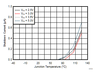
  Figure 2. Shutdown Current vs Junction Temperature
 7 Detailed Description
7.1 Overview
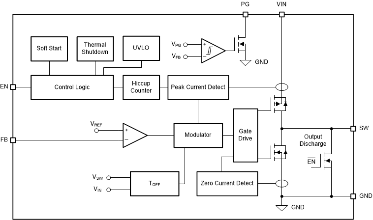
The TLV62585 is a high-efficiency synchronous step-down converter. The device operates with an adaptive off-time with peak current control scheme. The device operates at typically 1.5-MHz frequency pulse width modulation (PWM) at moderate to heavy load currents. Based on the VIN/VOUT ratio, a simple circuit sets the required off time for the low-side MOSFET. It makes the switching frequency relatively constant regardless of the variation of input voltage, output voltage, and load current.
7.2 Functional Block Diagram

7.3 Feature Description
7.3.1 Power Save Mode
The device automatically enters Power Save Mode to improve efficiency at light load when the inductor current becomes discontinuous. In Power Save Mode, the converter reduces switching frequency and minimizes current consumption. In Power Save Mode, the output voltage rises slightly above the nominal output voltage. This effect is minimized by increasing the output capacitor, or adding a feed forward capacitor, as shown in Figure 14.
7.3.2 100% Duty Cycle Low Dropout Operation
The device offers low input-to-output voltage difference by entering 100% duty cycle mode. In this mode, the high-side MOSFET switch is constantly turned on and the low-side MOSFET is switched off. The minimum input voltage to maintain output regulation, depending on the load current and output voltage, is calculated as:
- RDS(ON) = High side FET on-resistance
- RL = Inductor ohmic resistance (DCR)
7.3.3 Soft Start
After enabling the device, internal soft startup circuitry ramps up the output voltage which reaches nominal output voltage during a startup time. This avoids excessive inrush current and creates a smooth output voltage rise slope. It also prevents excessive voltage drops of primary cells and rechargeable batteries with high internal impedance.
The TLV62585 is able to start into a pre-biased output capacitor. The converter starts with the applied bias voltage and ramps the output voltage to its nominal value.
7.3.4 Switch Current Limit and Short Circuit Protection (HICCUP)
The switch current limit prevents the device from high inductor current and from drawing excessive current from the battery or input voltage rail. Excessive current might occur with a shorted or saturated inductor or a over load or shorted output circuit condition. If the inductor current reaches the threshold ILIM, the high-side MOSFET is turned off and the low-side MOSFET is turned on to ramp down the inductor current with an adaptive off-time.
When this switch current limits is triggered 32 times, the device reduces the current limit for further 32 cycles and then stops switching to protect the output. The device then automatically start a new startup after a typical delay time of 500 μs has passed. This is named HICCUP short circuit protection. The devices repeat this mode until the high load condition disappears. HICCUP protection is also enabled during the startup.
7.3.5 Undervoltage Lockout
To avoid misoperation of the device at low input voltages, an undervoltage lockout (UVLO) is implemented, which shuts down the device at voltages lower than VUVLO with a hysteresis of 150 mV.
7.3.6 Thermal Shutdown
The device goes into thermal shutdown and stops switching when the junction temperature exceeds TJSD. When the device temperature falls below the threshold by 20°C, the device returns to normal operation automatically.
7.4 Device Functional Modes
7.4.1 Enable and Disable
The device is enabled by setting the EN pin to a logic HIGH. Accordingly, shutdown mode is forced if the EN pin is pulled LOW with a shutdown current of typically 0.7 μA.
In shutdown mode, the internal power switches as well as the entire control circuitry are turned off. An internal output discharge FET discharges the output through the SW pin smoothly.
7.4.2 Power Good
The TLV62585 has a power good output. The power good goes high impedance once the output is above 95% of the nominal voltage, and is driven low once the output voltage falls below typically 90% of the nominal voltage. The PG pin is an open-drain output and is specified to sink up to 1 mA. The power good output requires a pull-up resistor connecting to any voltage rail less than 5.5 V. The PG signal can be used for sequencing of multiple rails by connecting it to the EN pin of other converters. Leave the PG pin unconnected when not used.
Table 1. PG Pin Logic
| DEVICE CONDITIONS | LOGIC STATUS | ||
|---|---|---|---|
| HIGH Z | LOW | ||
| Enable | EN = High, VFB ≥ VPG | √ | |
| EN = High, VFB ≤ VPG | √ | ||
| Shutdown | EN = Low | √ | |
| Thermal Shutdown | √ | ||
| UVLO | 1.4 V < VIN < 2.3 V | √ | |
| Power Supply Removal | VIN ≤ 1.4 V | √ | |
8 Application and Implementation
NOTE
Information in the following applications sections is not part of the TI component specification, and TI does not warrant its accuracy or completeness. TI’s customers are responsible for determining suitability of components for their purposes. Customers should validate and test their design implementation to confirm system functionality.
8.1 Application Information
The TLV62585 is a synchronous step-down converter in which output voltage is adjusted by component selection. The following section discusses the design of the external components to complete the power supply design for several input and output voltage options by using typical applications as a reference.
8.2 Typical Application
 Figure 4. 1.8-V Output Voltage Application
 8.2.1 Design Requirements
For this design example, use the parameters listed in Table 2 as the input parameters.
Table 2. Design Parameters
| DESIGN PARAMETER | EXAMPLE VALUE |
|---|---|
| Input voltage | 2.5 V to 5.5 V |
| Output voltage | 1.8 V |
| Maximum output current | 3 A |
Table 3 lists the components used for the example.
Table 3. List of Components(1)
| REFERENCE | DESCRIPTION | MANUFACTURER |
|---|---|---|
| C1 | 10 µF, Ceramic capacitor, 10 V, X7R, size 0805, GRM21BR71A106ME51 | Murata |
| C2 | 22 µF, Ceramic capacitor, 6.3 V, X7T, size 0805, GRM21BD70J226ME44 | Murata |
| C3 | Optional | Std |
| L1 | 1 µH, Power Inductor, size 4 mm × 4 mm × 1.5 mm, XFL4020-102ME | Coilcraft |
| R1 | Depending on the output voltage, 1%, size 0603; | Std |
| R2 | 100 kΩ, Chip resistor, 1/16 W, 1%, size 0603; | Std |
| R3 | 1 MΩ, Chip resistor, 1/16 W, 1%, size 0603 | Std |
8.2.2 Detailed Design Procedure
8.2.2.1 Custom Design With WEBENCH® Tools
Click here to create a custom design using the TLV62585 device with the WEBENCH® Power Designer.
- Start by entering the input voltage (VIN), output voltage (VOUT), and output current (IOUT) requirements.
- Optimize the design for key parameters such as efficiency, footprint, and cost using the optimizer dial.
- Compare the generated design with other possible solutions from Texas Instruments.
The WEBENCH Power Designer provides a customized schematic along with a list of materials with real-time pricing and component availability.
In most cases, these actions are available:
- Run electrical simulations to see important waveforms and circuit performance
- Run thermal simulations to understand board thermal performance
- Export customized schematic and layout into popular CAD formats
- Print PDF reports for the design, and share the design with colleagues
Get more information about WEBENCH tools at www.ti.com/WEBENCH.
8.2.2.2 Setting The Output Voltage
The output voltage is set by an external resistor divider according to Equation 2:

R2 must not be higher than 100 kΩ to achieve high efficiency at light load while providing acceptable noise sensitivity.
8.2.2.3 Output Filter Design
The inductor and the output capacitor together provide a low-pass filter. To simplify the selection process, Table 4 outlines possible inductor and capacitor value combinations for most applications.
Table 4. Matrix of Output Capacitor and Inductor Combinations
| NOMINAL L [µH](2) | NOMINAL COUT [µF](3)(4) | |||
|---|---|---|---|---|
| 10 | 22 | 47 | 100 | |
| 0.47 | ||||
| 1 | + | +(1) | + | |
| 2.2 | ||||
8.2.2.4 Inductor Selection
The main parameter for the inductor selection is the inductor value and then the saturation current of the inductor. To calculate the maximum inductor current under static load conditions, Equation 3 is given.

where
- IOUT,MAX = Maximum output current
- ΔIL = Inductor current ripple
- fSW = Switching frequency
- L = Inductor value
TI recommends choosing the saturation current for the inductor 20% to 30% higher than the IL,MAX, out of Equation 3. A higher inductor value is also useful to lower ripple current but increases the transient response time as well.
8.2.2.5 Input and Output Capacitor Selection
The architecture of the TLV62585 allows use of tiny ceramic-type output capacitors with low equivalent series resistance (ESR). These capacitors provide low output voltage ripple and are thus recommended. To keep its resistance up to high frequencies and to achieve narrow capacitance variation with temperature, it is recommended to use X7R or X5R dielectric.
The input capacitor is the low impedance energy source for the converter that helps provide stable operation. A low ESR multilayer ceramic capacitor is recommended for best filtering. For most applications, 10-μF input capacitor is sufficient; a larger value reduces input voltage ripple.
The TLV62585 is designed to operate with an output capacitor of 10 μF to 47 μF, as outlined in Table 4.
A feed forward capacitor reduces the output ripple in PSM and improves the load transient response. A 22-pF capacitor is good for the 1.8-V output typical application.
8.2.3 Application Curves
VIN = 5 V, VOUT = 1.8 V, TA = 25 ºC, unless otherwise noted.

| VOUT = 1.2 V |

| VOUT = 2.5 V |

| VIN = 5 V |

| VIN = 5 V |

| IOUT = 0.1 A |

| IOUT = 3 A |

| No Load |

| IOUT = 0.1 A to 3 A | C3 = 22 pF |

| IOUT = 0.1 A |

| VOUT = 1.8 V |

| VOUT = 3.3 V |

| VOUT = 1.8 V |

| IOUT = 1 A |

| IOUT = 0.1 A | C3 = 22 pF |

| ROUT = 0.6 Ω |

| IOUT = 0.1 A to 3 A |

| IOUT = 0.1 A |
9 Power Supply Recommendations
The device is designed to operate from an input voltage supply range from 2.5 V to 5.5 V. Ensure that the input power supply has a sufficient current rating for the application.
