SLVS514O April   2004  – June 2024 TPS2041B , TPS2042B , TPS2043B , TPS2044B , TPS2051B , TPS2052B , TPS2053B , TPS2054B

PRODUCTION DATA  

  1.   1
  2. Features
  3. Applications
  4. Description
  5. General Switch Catalog
  6. Pin Configuration and Functions
  7. Specifications
    1. 6.1 Absolute Maximum Ratings
    2. 6.2 ESD Ratings
    3. 6.3 Recommended Operating Conditions
    4. 6.4 Thermal Information
    5. 6.5 Electrical Characteristics
    6. 6.6 Typical Characteristics (All Devices Excluding TPS2051BDBV and TPS2052BD)
    7. 6.7 Typical Characteristics (TPS2051BDBV and TPS2052BD)
  8. Parameter Measurement Information
  9. Detailed Description
    1. 8.1 Overview
    2. 8.2 Functional Block Diagrams
    3. 8.3 Feature Description
      1. 8.3.1  Power Switch
      2. 8.3.2  Charge Pump
      3. 8.3.3  Driver
      4. 8.3.4  Enable ( ENx)
      5. 8.3.5  Enable (ENx)
      6. 8.3.6  Current Sense
      7. 8.3.7  Overcurrent
        1. 8.3.7.1 Overcurrent Conditions (TPS20x3BD, TPS20x4BD, and TPS20x2BDRB)
        2. 8.3.7.2 Overcurrent Conditions (TPS20x1B & TPS20x2B in D, DGN, and DBV packages)
      8. 8.3.8  Overcurrent ( OCx)
      9. 8.3.9  Thermal Sense
      10. 8.3.10 Undervoltage Lockout
    4. 8.4 Device Functional Modes
  10. Application and Implementation
    1. 9.1 Application Information
      1. 9.1.1 Universal Serial Bus (USB) Applications
    2. 9.2 Typical Application
      1. 9.2.1 Typical Application (TPS2042B)
        1. 9.2.1.1 Design Requirements
        2. 9.2.1.2 Detailed Design Procedure
          1. 9.2.1.2.1 Power-Supply Considerations
          2. 9.2.1.2.2 OC Response
        3. 9.2.1.3 Application Curves
      2. 9.2.2 Host and Self-Powered and Bus-Powered Hubs
        1. 9.2.2.1 Design Requirements
          1. 9.2.2.1.1 USB Power-Distribution Requirements
        2. 9.2.2.2 Detailed Design Procedure
          1. 9.2.2.2.1 Low-Power Bus-Powered and High-Power Bus-Powered Functions
        3. 9.2.2.3 Application Curves
      3. 9.2.3 Generic Hot-Plug Applications
        1. 9.2.3.1 Design Requirements
        2. 9.2.3.2 Detailed Design Procedure
        3. 9.2.3.3 Application Curves
  11. 10Power Supply Recommendations
    1. 10.1 Undervoltage Lockout (UVLO)
  12. 11Layout
    1. 11.1 Layout Guidelines
    2. 11.2 Layout Example
    3. 11.3 Power Dissipation
    4. 11.4 Thermal Protection
  13. 12Device and Documentation Support
    1. 12.1 Receiving Notification of Documentation Updates
    2. 12.2 Support Resources
    3. 12.3 Trademarks
    4. 12.4 Electrostatic Discharge Caution
    5. 12.5 Glossary
  14. 13Revision History
  15. 14Mechanical, Packaging, and Orderable Information

Package Options

Mechanical Data (Package|Pins)
Thermal pad, mechanical data (Package|Pins)
Orderable Information

Generic Hot-Plug Applications

In many applications it may be necessary to remove modules or pc boards while the main unit is still operating. These are considered hot-plug applications. Such implementations require the control of current surges seen by the main power supply and the card being inserted. The most effective way to control these surges is to limit and slowly ramp the current and voltage being applied to the card, similar to the way in which a power supply normally turns on. Due to the controlled rise times and fall times of the TPS20xxB, these devices can be used to provide a softer start-up to devices being hot-plugged into a powered system. The UVLO feature of the TPS20xxB also ensures that the switch is off after the card has been removed, and that the switch is off during the next insertion. The UVLO feature insures a soft start with a controlled rise time for every insertion of the card or module.
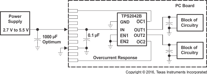
TPS2041B TPS2042B TPS2043B TPS2044B  TPS2051B TPS2052B TPS2053B TPS2054B Typical Hot-Plug Implementation (Example, TPS2042B) Figure 9-26 Typical Hot-Plug Implementation (Example, TPS2042B)

By placing the TPS20xxB between the VCC input and the rest of the circuitry, the input power reaches these devices first after insertion. The typical rise time of the switch is approximately 1 ms, providing a slow voltage ramp at the output of the device. This implementation controls system surge currents and provides a hot-plugging mechanism for any device.