SLVSCH2 July 2014 TPS2105-EP
PRODUCTION DATA.
- 1 Features
- 2 Applications
- 3 Description
- 4 Revision History
- 5 Pin Configuration and Functions
- 6 Specifications
- 7 Detailed Description
- 8 Application and Implementation
- 9 Power Supply Recommendations
- 10Layout
- 11Device and Documentation Support
- 12Mechanical, Packaging, and Orderable Information
Package Options
Mechanical Data (Package|Pins)
- DBV|5
Thermal pad, mechanical data (Package|Pins)
Orderable Information
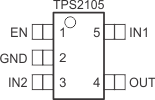
5 Pin Configuration and Functions
5-Pin SOT
DBV Package
(Top View)

Pin Functions
| PIN | I/O | DESCRIPTION | |
|---|---|---|---|
| NAME | NO. | ||
| EN | 1 | I | Active-high enable for IN1-OUT switch |
| GND | 2 | I | Ground |
| IN1(1) | 5 | I | Main input voltage, NMOS drain (250 mΩ), requires 0.22-µF bypass |
| IN2(1) | 3 | I | Auxiliary input voltage, PMOS drain (1.3 Ω), requires 0.22-µF bypass |
| OUT | 4 | O | Power switch output |
(1) Unused INx should not be grounded.
5.1 Function Table
| TPS2105 | |||
|---|---|---|---|
| VIN1 | VIN2 | EN | OUT |
| 0 V | 0 V | XX(1) | GND |
| 0 V | 5 V | h | GND |
| 5 V | 0 V | h | VIN1 |
| 5 V | 5 V | h | VIN1 |
| 0 V | 5 V | l | VIN2 |
| 5 V | 0 V | l | VIN2 |
| 5 V | 5 V | l | VIN2 |
(1) XX = Don't care